Operator control apparatus, in particular for electronic domestic appliance

A technology of operating devices and household equipment, applied in the direction of electronic switches, electrical components, pulse technology, etc.

Active Publication Date: 2018-12-21
DIEHL AKO STIFTUNG
View PDF13 Cites 0 Cited by
  • Summary
  • Abstract
  • Description
  • Claims
  • Application Information

AI Technical Summary

Problems solved by technology

However, these traditional optical slide contro

Method used


Image

  • Operator control apparatus, in particular for electronic domestic appliance

Examples


Embodiment Construction

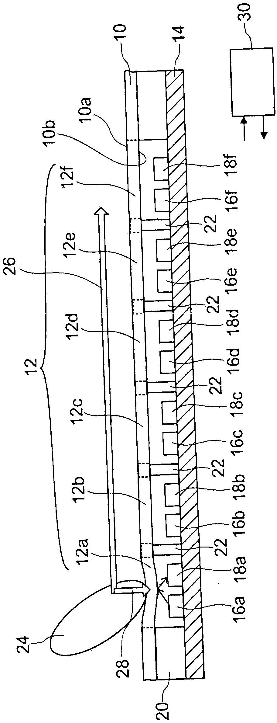
[0031] The operating device has, for example, a cover plate 10 in the form of, for example, an operating panel of an electronic household appliance. The cover plate 10 has a user side 10a facing the user (at the figure 1 top center) and the back side 10b facing away from the user (at the figure 1 The user side corresponds to the outer side of the operation panel or the device, and the back side corresponds to the inner side of the operation panel or the device. The cover plate 10 is made of plastic or metal, for example.

[0032] The cover plate 10 has an operating area 12 which defines for the user a sliding control which can be manipulated by the user. The operation area 12 includes a plurality of operation sections 12a to 12f, which are arranged along an operation line (eg, linear, arcuate, circular, etc.). The actuating sections 12a to 12f are integrated into the cover plate 10 or are formed in one piece with the cover plate or are respectively embedded in the cover pla...


PUM


Abstract

An operator control apparatus which is designed as a slide controller has: a covering plate (10) with a user side (10a) which faces a user, wherein the covering plate (10) has an operator control panel (12) with a plurality of operator control panel sections (12a-12f) which are arranged along an operator control line; a plurality of optical sensors, wherein at least one transmitter (16a-16f) of the plurality of optical sensors for emitting electromagnetic radiation and at least one receiver (18a-18f) of the plurality of optical sensors for detecting electromagnetic radiation are associated with each of the plurality of operator control panel sections (12a-12f); and a control electronics system (30) for analyzing measurement signals which are generated by the at least one receiver (18a-18f)of the plurality of optical sensors. The plurality of operator control panel sections (12a-12f) of the operator control panel (12) of the covering plate (10) are in this case each configured in sucha way that they can be at least partially elastically deformed and/or moved by a pressure force (28) from the user side (10a) of the covering plate (10), and in that they at least partially reflect radiation which is emitted by the transmitter (16a-16f) which is associated with them. The at least one receiver (18a-18f) is arranged and/or designed in such a way that it allows spatially resolved detection of the radiation which is reflected by the operator control panel section (12a-12f) with which the at least one receiver is associated, and the control electronics system (30) detects operationof the operator control panel section (12a-12f) with which the at least one receiver is associated, depending on a detection location of the reflected radiation on this receiver (18a-18f).

Description

technical field [0001] The invention relates to an operating device, in particular an operating device for electronic household appliances. Background technique [0002] Operating devices with touch- and / or proximity-sensitive operating elements generally have a rigid cover plate, which defines the operating area and in which the cover plate is designed to be at least partially transparent to infrared or visible radiation of. The optical sensor comprises at least one transmitter for emitting electromagnetic radiation, which is emitted by the transmitter, propagates through the operating area and is placed on the cover by the operating element, eg a user, and at least one receiver for detecting the electromagnetic radiation Finger reflection on the user side of the board. Touch- and / or proximity-sensitive operating devices, which are designed as slide controls or sliders, usually have a cover plate with a user side facing the user, wherein the cover plate has a The operati...

Claims


Application Information

Patent Timeline
IPC IPC(8): H03K17/969H03K17/96
CPCH03K17/9636H03K17/969H03K2217/96066
Inventor A·迈格勒B·富格J·林斯楚斯R·斯托尔T·弗罗梅尔特M·施温德
Owner DIEHL AKO STIFTUNG
Why Eureka
Try Eureka