Earphone testing

A technology of earphones and test stations, applied in earphone/earphone accessories, earphones to reduce environmental noise, mechanical equipment, etc., can solve the problem that the test system occupies a considerable space and so on

Active Publication Date: 2018-12-21
DSP GROUP
View PDF6 Cites 6 Cited by
  • Summary
  • Abstract
  • Description
  • Claims
  • Application Information

AI Technical Summary

Problems solved by technology

In addition, the test system takes up considerable space, especially when it must be acoustically penetrated by a carefully controlled external noise field to test feed-forward noise control or other aspects of sound transmission through or through the headset

Method used


Image

  • Earphone testing
  • Earphone testing
  • Earphone testing

Examples


Embodiment Construction

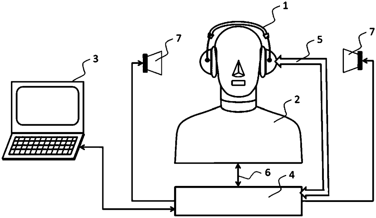
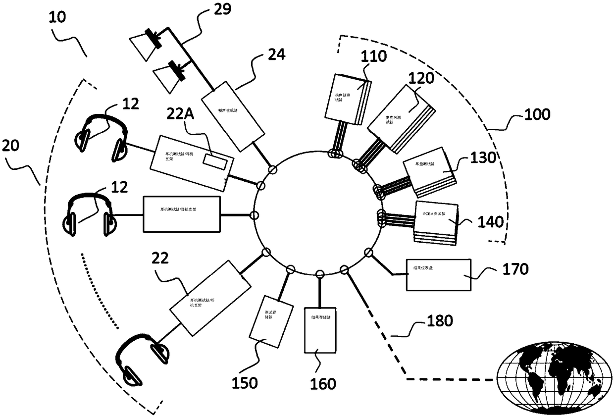
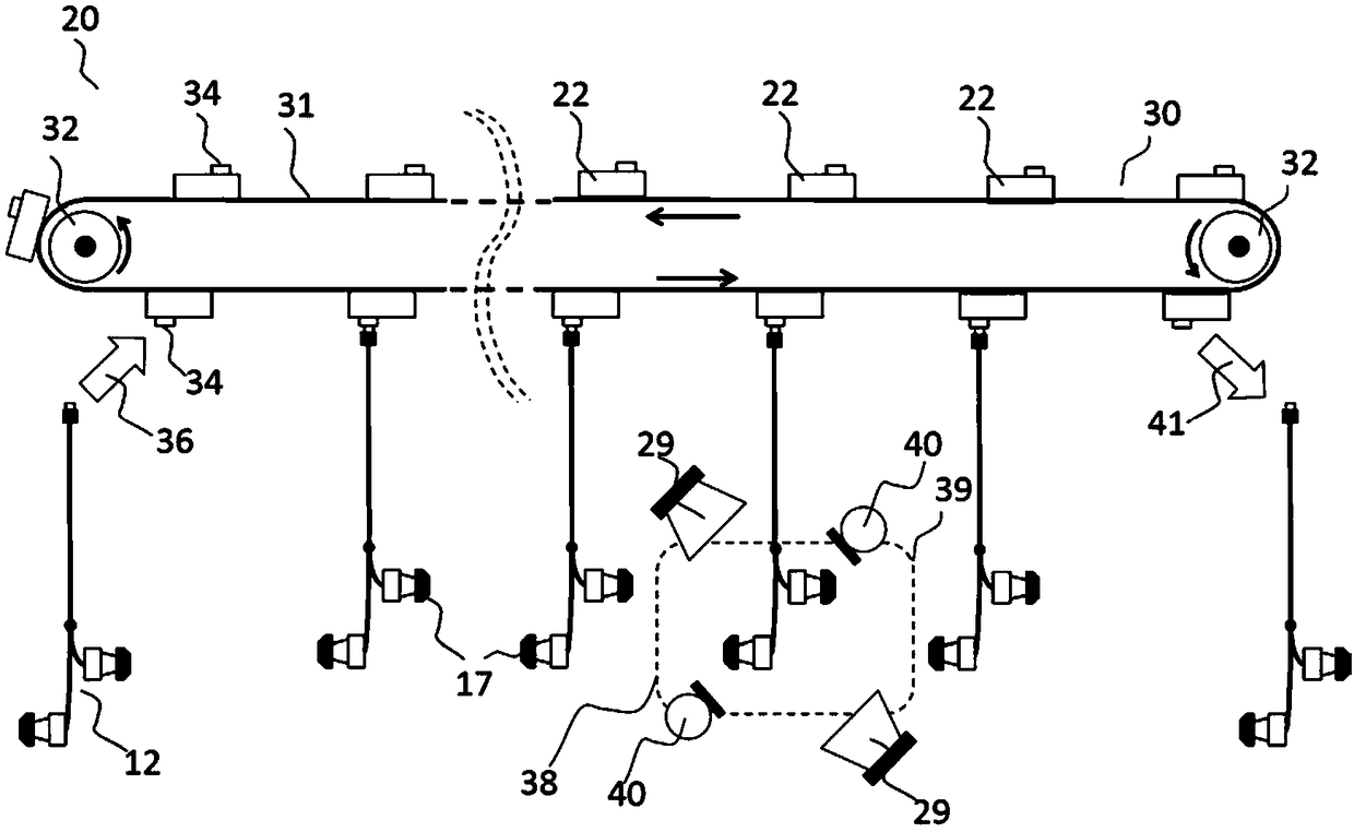
[0078] figure 2 A headphone testing system 10 is shown comprising a headphone testing assembly 20 having a plurality of test stations 22 for linking a headphone 12 under test and a common noise generator 24 driving an array of loudspeakers 29 . Each testing component 20 includes a testing module 22A operable to follow the testing procedure defined on the individual testing routine source component 150, which testing module 22A allows for collective modification of the testing procedure undergone by all earphone devices 12 under test. Similarly, results are accumulated at the central location 160 . The local operation of the test system 10 can be monitored at the operator interface 170, and the communication path 180 allows both global distribution of data originating from the system as well as remote control of the system.

[0079] It should be noted that testing station 22 is not a simple repeated instance of the system of FIG. 1 . Instead, it is only implemented as an inte...


PUM


Abstract

An earphone test system (20) comprising: a plurality of test stations (22) each operative to perform a function during testing of an earphone device (12) coupled thereto, wherein during testing of earphone devices (12) coupled to the plurality of test stations (22) the earphone test system (20) is operative to expose each of the plurality of test stations (22) to a noise field generated by a common noise field source(29).

Description

technical field [0001] The present invention relates to an earphone testing system and a method of testing an earphone device, and is particularly but not exclusively intended to test an earphone device with an active noise reduction (ANR) function. Background technique [0002] Earphones (e.g., circumaural or on-ear earphones of the headphone type that are connected together by a headband to form a headphone type or in-ear / in-canal earphones configured to be placed at the entrance of the user's ear or in the auditory canal) are known in the art is well known. Active headphone systems incorporating active headphone drivers to provide advanced active features such as Active Noise Reduction (ANR) or binaural monitoring are also well known in the art. ANR techniques provide the ability to cancel (at least some useful parts of) unwanted external sounds via feed-forward control and / or provide the ability to cancel (at least some useful parts of) unwanted sounds sensed by interna...

Claims


Application Information

Patent Timeline
Patent Type & Authority Applications(China)
IPC IPC(8): H04R29/00H04R1/10
CPCH04R1/1083H04R29/00E21B43/127F04B47/12F04B53/125
Inventor 保罗·达林顿本·斯凯尔顿
Owner DSP GROUP
Why Eureka
Try Eureka