Automatic cleaning device for impeller

An automatic cleaning and impeller technology, applied in the directions of dry gas arrangement, cleaning method and utensils, cleaning method using tools, etc., can solve the problem of not completely cleaning the dust on the surface of the impeller

Active Publication Date: 2018-12-25
安徽德姆勒科技股份有限公司
View PDF7 Cites 11 Cited by
  • Summary
  • Abstract
  • Description
  • Claims
  • Application Information

AI Technical Summary

Problems solved by technology

[0005] The present invention intends to provide an automatic impeller cleaning device to overcome the problem in the prior art that the dust on the surface of the impeller cannot be completely cleaned

Method used


Image

  • Automatic cleaning device for impeller
  • Automatic cleaning device for impeller
  • Automatic cleaning device for impeller

Examples


Embodiment Construction

[0025] The following is further described in detail through specific implementation methods:

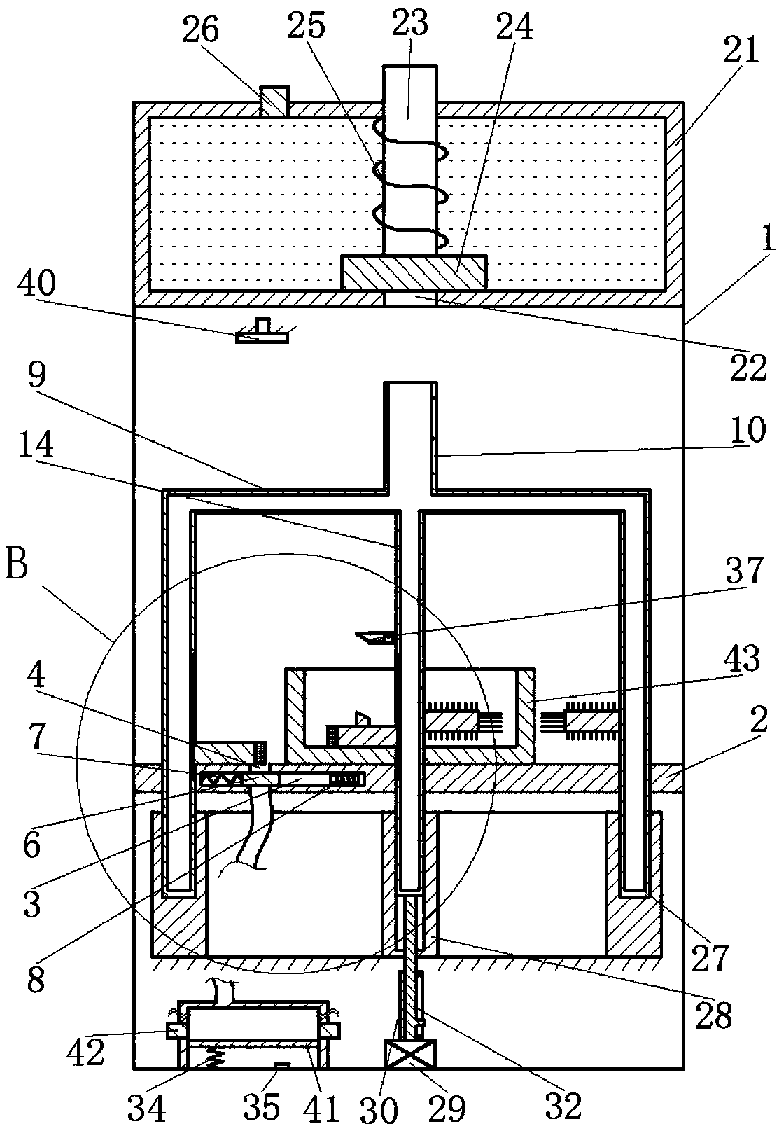
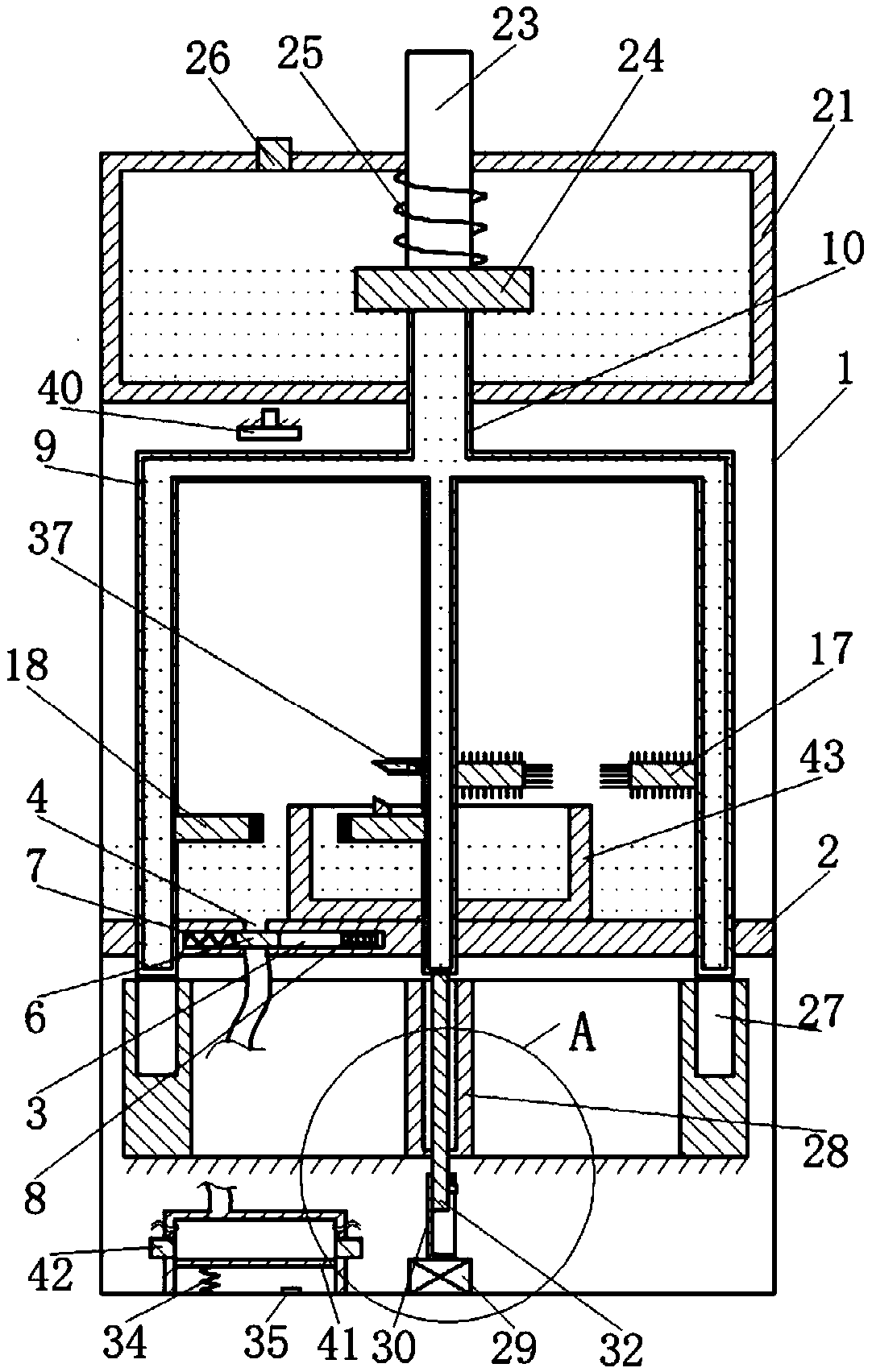
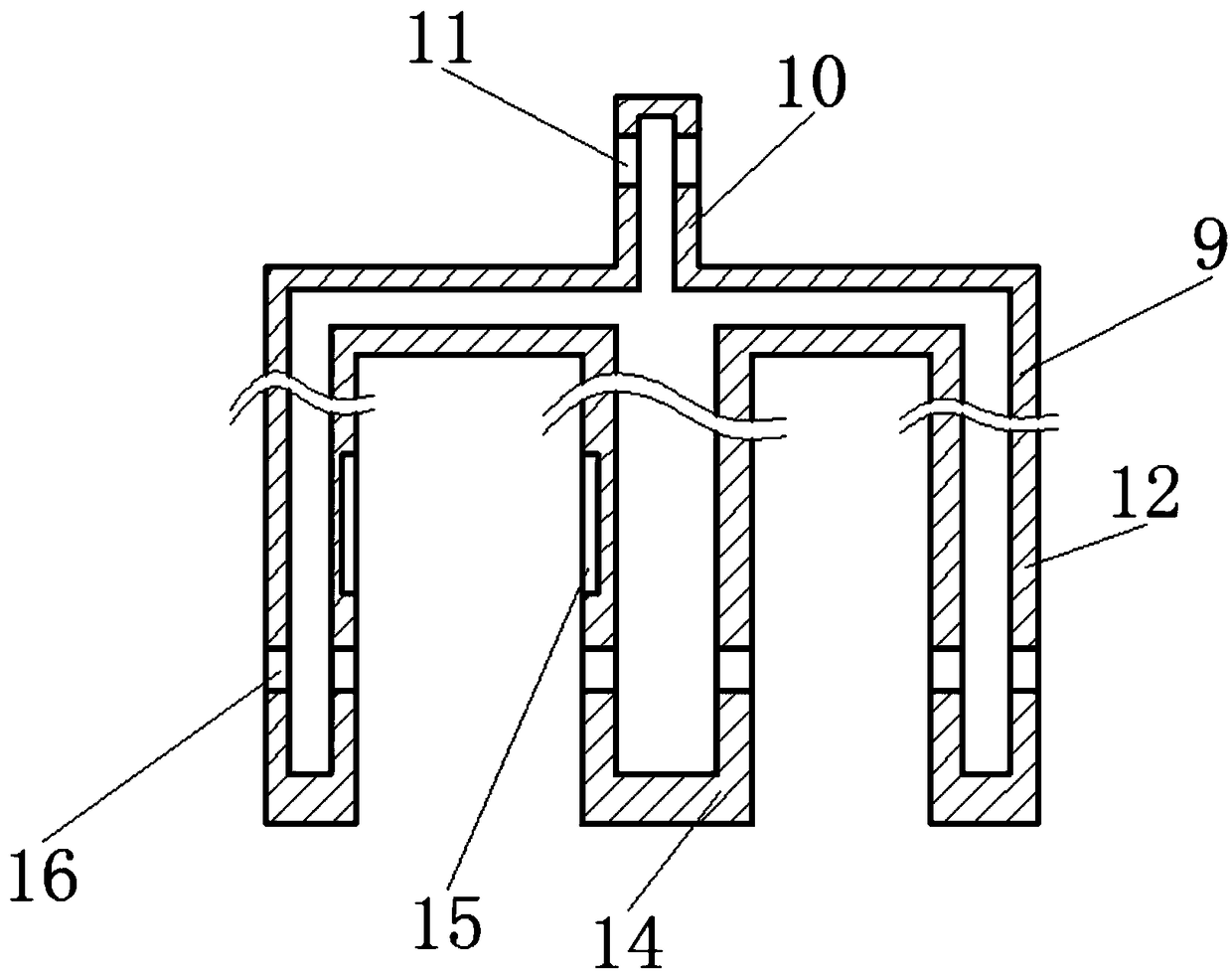
[0026] The reference signs in the drawings of the description include: housing 1, partition plate 2, first cavity 3, opening 4, outlet pipe 5, slider 6, first spring 7, electromagnet 8, support column 9, water inlet column 10 , water inlet 11, side column 12, third spring 13, middle column 14, vertical chute 15, first water outlet 16, brush 17, foam board 18, sponge 19, first wedge block 20, water tank 21 , second water outlet 22, sealing column 23, baffle plate 24, return spring 25, water cover 26, annular chute 27, sleeve 28, motor 29, limit cylinder 30, limit groove 31, slide rod 32, convex Play 33, the second spring 34, fan switch 35, hollow tube 36, the second wedge block 37, electromagnetic switch 38, blower 40, piston 41, drain cover 42, impeller 43.

[0027] The embodiment is basically as attached figure 1 To attach Figure 6Shown: an automatic impeller cleaning device, in...


PUM


Abstract

The invention relates to the technical field of fan cleaning and discloses an automatic cleaning device for an impeller. The cleaning device comprises a housing, a partition plate divides the housinginto an upper chamber and a lower chamber and is rotatably connected in the housing and internally provided with a first cavity, an opening, a water outlet pipe and a sliding block, and an electromagnet is fixedly connected in the first cavity; the upper chamber is internally provided with a support column and a water inlet column, the support column comprises side columns and a middle column, andthe middle column is provided with an electromagnetic switch assembly; the upper chamber is internally provided with brushes, floating plates and an air blower, the floating plates are fixedly connected with sponges and a first wedge-shaped block; a water tank is arranged on the top of the upper chamber and slidingly connected with a sealing column, a baffle and a reset spring; the lower chamberis internally provided with a circular base, a sleeve and a motor, and a retractable rod assembly is arranged at an output end of the motor; a piston cylinder, a piston and a second spring are arranged in the lower chamber, and a fan switch is arranged in a second chamber. Rotation of the support column drives the brushes and the sponges to rotate, so that the inner and outer surfaces of the impeller are cleaned.

Description

technical field [0001] The invention relates to the technical field of fan cleaning, in particular to an automatic impeller cleaning device. Background technique [0002] After the fan is used for a long time, a lot of dust will stick to the impeller. In order not to affect the normal blowing effect of the fan, the impeller needs to be cleaned. At present, the impeller is usually cleaned manually, but manual cleaning is time-consuming and laborious, and the cleaning effect is not good. [0003] In order to overcome the above-mentioned defects of manually cleaning the impeller, the patent application number: 201410811631.1, the patent document of authorized announcement number: CN104550110B discloses a fan impeller cleaning machine, including a shell that is divided into upper and lower two-layer spaces. There is a drainage device for draining the water in the upper space out of the shell, a motor is installed in the lower space, a water injection port is provided in the upp...

Claims


Application Information

Patent Timeline
Patent Type & Authority Applications(China)
IPC IPC(8): B08B1/04B08B3/04F26B21/00
CPCB08B1/002B08B1/006B08B1/04B08B3/04F26B21/00
Inventor 岑露明
Owner 安徽德姆勒科技股份有限公司
Why Eureka
Try Eureka