Diagonal hole drilling mold for nozzle ring of engine

An oblique hole drilling die and nozzle ring technology, applied in boring/drilling, drilling/drilling equipment, drilling dies for workpieces, etc., can solve the problems of difficult debugging of drilling dies, difficulty in repairing, inconvenient operation, etc. , to achieve the effect of reliable positioning, easy maintenance and convenient operation

Active Publication Date: 2018-12-25
XIAN SPACE ENGINE CO LTD
View PDF5 Cites 9 Cited by
  • Summary
  • Abstract
  • Description
  • Claims
  • Application Information

AI Technical Summary

Problems solved by technology

The key to machining the slanted hole of the engine nozzle ring is to ensure the angle of the slanted hole and the diameter of the index circle at the entrance and exit. However, one of the defects of the existing drilling mold for the slanted hole of the nozzle ring is that it is inconvenient to operate.
When locking and loosening the mandrel with a tangential clamping sleeve, there is interference between the handle and the indexing plate, and it is necessary to change the force application position of the handle in the middle. Multiple processing, this kind of clamping method is easy to cause cumbersome operation problems; the second defect is that it is difficult to repair
When there is an out-of-tolerance phenomenon in the drilling jig, since the parts and the positioning plate are matched by the shaft hole, and the positioning reference of the tooling is the center hole of the positioning plate, the relative position of the parts and the positioning plate is fixed, and there is irreversibility in the repair, so it is difficult to debug the drilling jig

Method used


Image

  • Diagonal hole drilling mold for nozzle ring of engine
  • Diagonal hole drilling mold for nozzle ring of engine
  • Diagonal hole drilling mold for nozzle ring of engine

Examples


Embodiment Construction

[0027] The present invention will be described below in conjunction with the accompanying drawings.

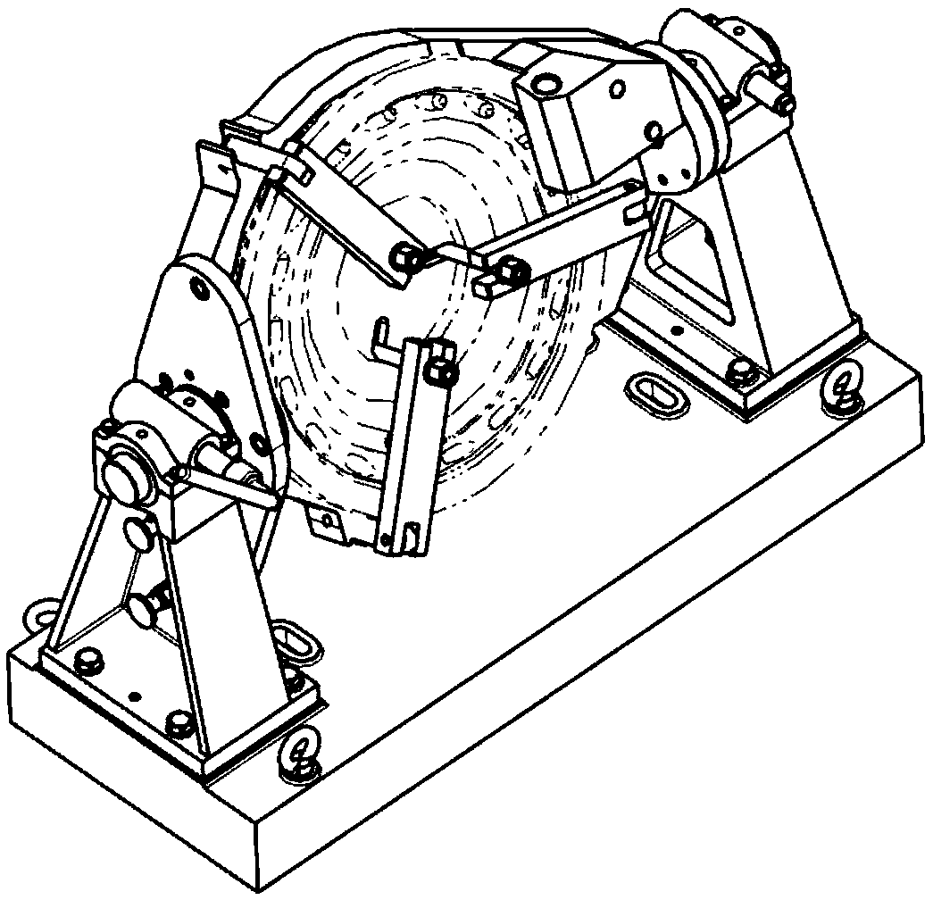
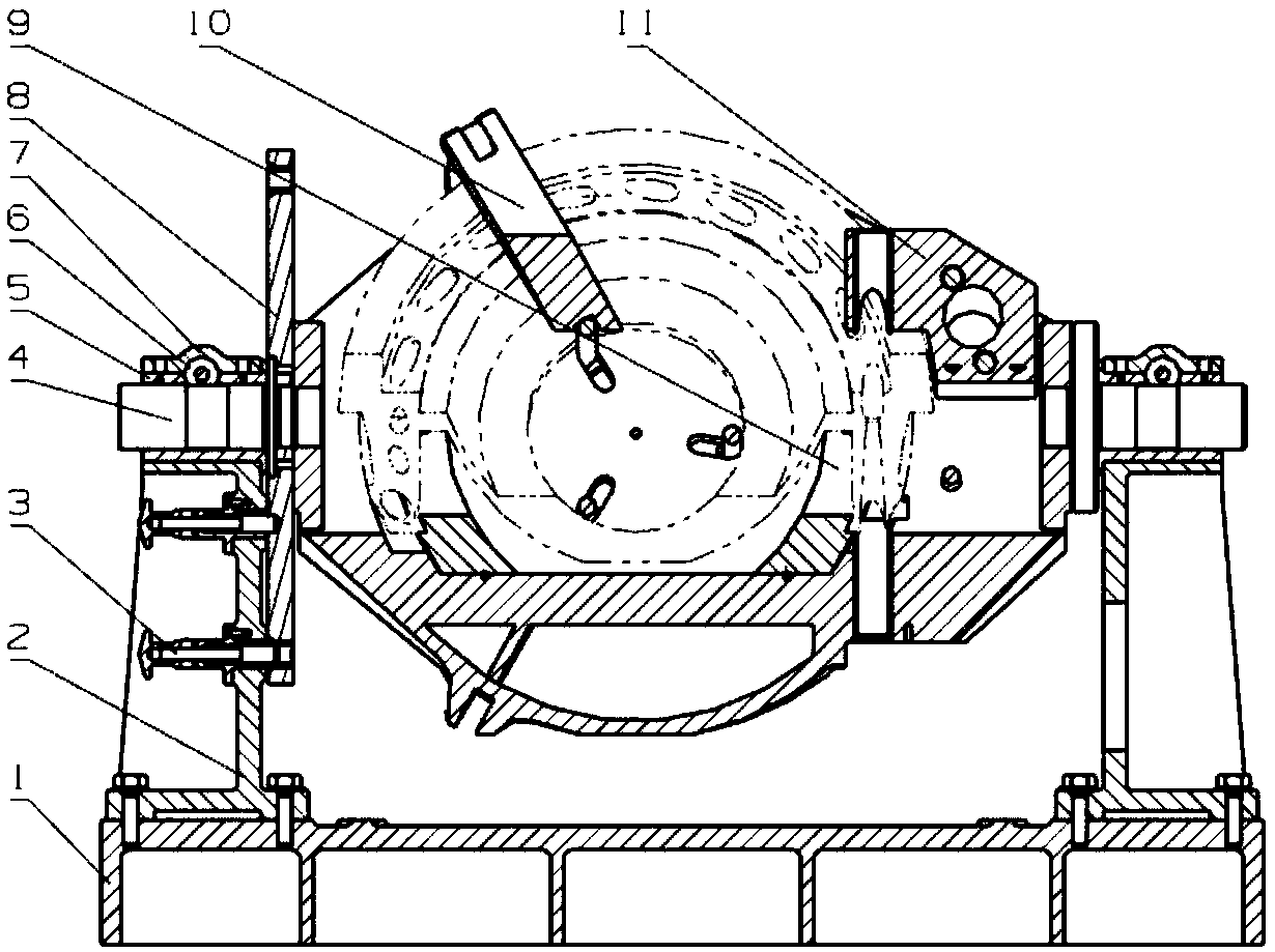
[0028] Such as Figure 2 to Figure 4 Shown is the engine nozzle ring oblique hole drilling template of the present invention, i.e. the basic form of the present invention. Engine nozzle ring inclined hole drilling template includes base 1, support 2, locator 3, mandrel 4, bearing 5, tangential clamping sleeve 6, bearing cap 7, indexing plate 8, positioning ring 9, pressure plate 10, upper Support plate 11, positioning plate 12, handle nut 13, drill sleeve 15, left and right support 2 are fixed on the base 1 by pins and bolts, bearing 5 is installed in the center hole of the upper end of the left and right support, mandrel 4 and positioning plate 12 are fixed by pins It is connected with bolts and placed in the bearing holes at both ends respectively. The bearing cover 7 is located at the upper end of the support 2. The tangential clamping sleeve 6 is located between the beari...


PUM


Abstract

The invention relates to a diagonal hole drilling mold for a nozzle ring of an engine. The diagonal hole drilling mold comprises a base, supports, a positioner, a mandrel, a bearing, a tangential clamping cover, a bearing cap, an indexing plate and the like. The left and right supports are fixed to the base through pins and bolts, the bearing is mounted in center holes in the upper ends of the left and right supports, the mandrel is connected with a positioning plate through the pins and the bolts and is placed in bearing holes at two ends separately, the bearing cap is located at the upper end of a bracket, the tangential clamping cover is located between the bearing cap and the bearing, and one end of the tangential clamping cover is connected with a handle nut. The mandrel is locked during work. The indexing plate is connected with a lug at the left side of the positioning plate through the pins and the bolts, and a special angle is formed between the indexing plate and the lug. When a drilling mold works, a diagonal hole is processed from the front face and the back face by positioning the drilling mold through positioning holes in two ends of the indexing plate position. Positioning rings and the positioning plate are connected through the pins and the bolts, and the positioning is achieved by the cooperation of an excircle and an inner hole of the nozzle ring. The diagonal hole drilling mold has the advantages of being high in positioning precision, convenient to operate, high in practicality and the like, and can be used for processing complex diagonal holes.

Description

technical field [0001] The invention relates to an inclined hole drilling mold, in particular to an engine nozzle ring inclined hole drilling mold. Background technique [0002] Such as figure 1 As shown, it is the rough drawing of the engine nozzle ring, the structure is complex, and the inclined hole to be processed is located on the stepped circle of the bottom surface. The specific position is as follows figure 2 shown. The key to machining the oblique hole of the engine nozzle ring is to ensure the angle of the oblique hole and the diameter of the index circle at the entrance and exit. However, one of the defects of the existing drilling mold for the oblique hole of the nozzle ring is that it is inconvenient to operate. When locking and loosening the mandrel with a tangential clamping sleeve, there is interference between the handle and the indexing plate, and it is necessary to change the force application position of the handle in the middle. This kind of clamping...

Claims


Application Information

Patent Timeline
Patent Type & Authority Applications(China)
IPC IPC(8): B23B47/28B23Q3/06B23B41/00B23Q16/02
Inventor 贺崇森王东陈磊刘广续周传磊
Owner XIAN SPACE ENGINE CO LTD
Why Eureka
Try Eureka