Eureka AIR delivers breakthrough ideas for toughest innovation challenges, trusted by R&D personnel around the world.

Multifunctional cutting device for building decoration

A technology for architectural decoration and cutting devices, which is applied in the direction of shearing devices, shearing machine equipment, metal processing equipment, etc., and can solve the problems of large devices that cannot be moved, cutting knives are fixed, and cannot be used in various cutting conditions.

Inactive Publication Date: 2018-12-25
刘丽军
View PDF7 Cites 3 Cited by
  • Summary
  • Abstract
  • Description
  • Claims
  • Application Information

AI Technical Summary

Problems solved by technology

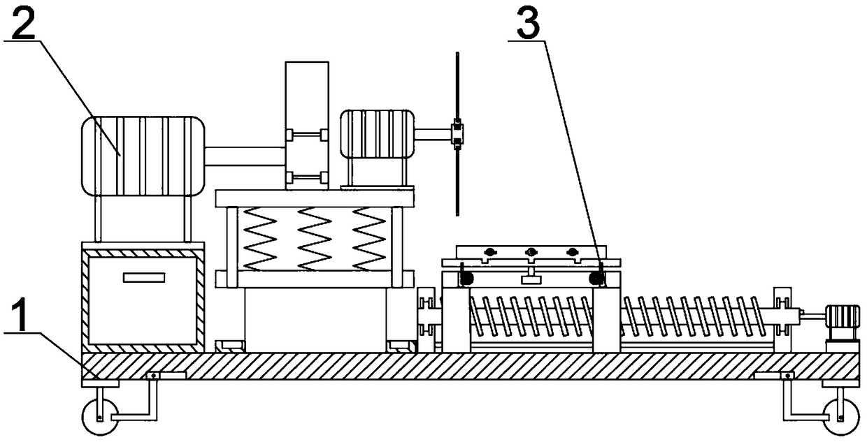
[0002] In architectural decoration work, it is often encountered in cutting materials. Traditional cutting tools are laborious to move plates, etc., and the device is too large to move, and the cutting knife is fixed, which cannot be applied to various cutting conditions. Therefore, this design is designed Multifunctional cutting device for architectural decoration

Method used


Image

  • Multifunctional cutting device for building decoration
  • Multifunctional cutting device for building decoration
  • Multifunctional cutting device for building decoration

Examples


specific Embodiment approach 1

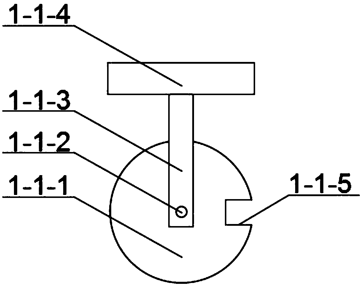
[0040] Combine below figure 1 , figure 2 , image 3 , Figure 4 , Figure 5 , Figure 6 , Figure 7 , Figure 8 , Figure 9 , Figure 10 , Figure 11 , Figure 12 , Figure 13 , Figure 14 Describe this embodiment. The present invention relates to a cutting device, more specifically a multifunctional cutting device for architectural decoration, which includes a movable chassis mechanism 1, a liftable cutting mechanism 2, and a movable cutting platform mechanism 3. The device can Realize the cutting function, the tool can be lifted and lowered automatically, the device can move the plate for cutting, the device can rotate the plate for cutting, the device can store construction tools, the device can move, and the device can realize the parking function.

[0041] Mobile chassis mechanism 1 comprises mobile wheel mechanism 1-1, parking slide bar mechanism 1-2, chassis 1-3, and mobile wheel mechanism 1-1 is positioned at the below of chassis 1-3, and mobile wheel mech...

specific Embodiment approach 2

[0055] Combine below figure 1 , figure 2 , image 3 , Figure 4 , Figure 5 , Figure 6 , Figure 7 , Figure 8 , Figure 9 , Figure 10 , Figure 11 , Figure 12 , Figure 13 , Figure 14 This embodiment will be described, and the first embodiment will be further described in this embodiment. The number of the moving wheel mechanism 1-1 and the parking slider mechanism 1-2 is four.

specific Embodiment approach 3

[0056] Combine below figure 1 , figure 2 , image 3 , Figure 4 , Figure 5 , Figure 6 , Figure 7 , Figure 8 , Figure 9 , Figure 10 , Figure 11 , Figure 12 , Figure 13 , Figure 14 This embodiment will be described. This embodiment will further describe the first embodiment. The material of the compression spring 2-2-5 is high carbon steel.


PUM


Abstract

The invention relates to a cutting device, in particular to a multifunctional cutting device for building decoration. The multifunctional cutting device comprises a moving bottom frame mechanism, a lifting cutting mechanism and a movable cutting platform mechanism. The multifunctional cutting device can realize a cutting function, and a cutter can ascend and descend automatically; the multifunctional cutting device can move a plate to conduct cutting, can rotate the plate to conduct cutting, can store construction utensils, can move and can realize a parking function; the lifting cutting mechanism is located above the moving bottom frame mechanism and connected with the moving bottom frame mechanism through bolts; and the movable cutting platform mechanism is located on the upper portion of the moving bottom frame mechanism and connected with the moving bottom frame mechanism through bolts.

Description

technical field [0001] The invention relates to a cutting device, in particular to a multifunctional cutting device for architectural decoration. Background technique [0002] In architectural decoration work, it is often encountered in cutting materials. Traditional cutting tools are laborious to move plates, etc., and the device is too large to move, and the cutting knife is fixed, which cannot be applied to various cutting conditions. Therefore, this design is designed Multifunctional cutting device for architectural decoration. Contents of the invention [0003] The main technical problem to be solved by the present invention is to provide a multifunctional cutting device for architectural decoration, the device can realize the cutting function, the cutter can be lifted and lowered automatically, the device can move the plate for cutting, the device can rotate the plate for cutting, and the device can store construction tools. The device can move, and the device can r...

Claims


Application Information

Patent Timeline
Patent Type & Authority Applications(China)
IPC IPC(8): B23D19/00
CPCB23D19/00
Inventor 刘丽军
Owner 刘丽军
Why Eureka
Eureka Blog
Learn More