Double-layer combination flap valve

A flap valve, double-layer technology, applied in the direction of conveyor objects, transportation and packaging, can solve the problems of aggravating material accumulation, increase production, installation cost, poor stability, etc., to avoid material accumulation, enhance sealing performance, and stabilize strong effect

Active Publication Date: 2018-12-25
CHANGSHA UNIVERSITY OF SCIENCE AND TECHNOLOGY
View PDF6 Cites 2 Cited by
  • Summary
  • Abstract
  • Description
  • Claims
  • Application Information

AI Technical Summary

Problems solved by technology

[0004] 1. The flap valve of the prior art has a single function or each function is independent, which often occupies a large space and increases the cost of production and installation
[0005] 2. Due to the limitation of the installation space, it is difficult for the flap valve of the prior art to realize the function of uniform mixing and stirring, so that the mixing degree of each sample material in the final molding is different.
[0006] 3. The flap valve of the prior art is difficult to realize the function of precisely controlling the amount of material to be discharged during the discharge process, and cannot meet the requirements of modern material discharge.
[0007] 4. With the flap valve of the prior art, after the installation is completed and the structure is fixed, it is difficult to realize non-disassembly adjustment, resulting in uneven blanking and difficulty in adapting to different working conditions
[0008] 5. In the flap valve of the prior art, an external driving device is used as an auxiliary part, which is fixed or has high cost or poor stability
[0009] 6. In the flap valve of the prior art, materials are easy to accumulate on the valve plate, and the sealing performance is not enough. After using parts such as sealing rings, the sealing performance is improved, but the material accumulation is further aggravated
[0010] 7. The flap valve in the prior art has a single function, and it is difficult to realize the combined function

Method used


Image

  • Double-layer combination flap valve
  • Double-layer combination flap valve
  • Double-layer combination flap valve

Examples


Embodiment Construction

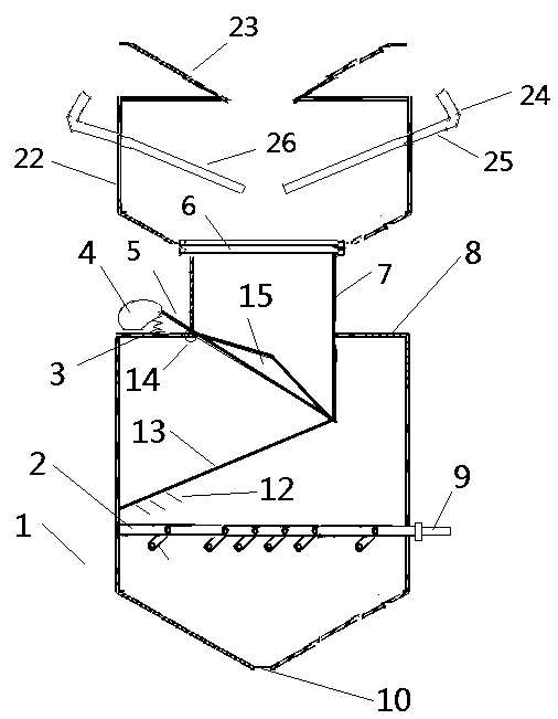
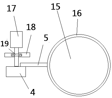
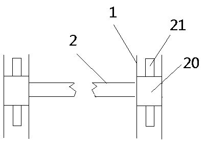
[0039] As shown in the figure: a double-layer combined flap valve, including a first blanking valve and a second blanking valve, the first blanking valve is located on the upper layer, and the second blanking valve is located on the lower layer; the first blanking valve It includes an upper cylinder, a funnel, a corner, a lever, and a left and right flap; the lever can be controlled to rotate through the corner, thereby driving the left and right flaps to rotate, thereby opening or closing the first blanking valve. A funnel is arranged on the top of the cylinder, which is convenient for receiving materials; the second blanking valve includes a lower cylinder, a baffle, a spring, a roulette, a support rod, a flange, a straight cylinder, a cylinder shoulder, a cylinder, a discharge port, a leaf Plate, comb tooth, telescopic rod, fulcrum, conical disc, damping ring, servo motor, bracket, ferrule, rotating ring, protrusion; The first blanking valve and the second blanking valve ar...


PUM


Abstract

The invention relates to a double-layer combination flap valve which includes a first falling valve and a second falling valve. The first falling valve is located on the upper layer, the second falling valve is located on the lower layer, the first falling valve comprises an upper layer barrel body, a funnel, bends, levers and left and right flapping plates, the bends can control the levels to rotate, thus the left and right flapping plates are driven to rotate, and then the first falling valve is opened or closed; and the funnel is arranged on the upper portion of the upper layer barrel bodyfor receiving materials conveniently, the second falling valve comprises a lower layer barrel body, a partition plate, a spring, a wheel disc, a supporting rod, a flange, a straight barrel, a barrel shoulder, an air cylinder, a discharging port, a blade plate, comb teeth, telescopic rods, a fulcrum, a conical disc, a damping ring, a servo motor, a support, a hoop, rotating rings and bulges, the lower portion of the upper layer barrel body contracts, and the first falling valve and the second falling valve are mutually connected by an end port formed by contraction through the flange.

Description

technical field [0001] The invention relates to the related field of medium conveying control, in particular to a double-layer combined flap valve. Background technique [0002] In the process of conveying various materials, flap valve, unloading valve and blanking valve are commonly used terminal links; the materials involved are different, including minerals, sand, grain, etc., for various The requirements for materials and blanking are different. [0003] In actual use, the existing flap valves, blanking valves and discharge valves have the following problems: [0004] 1. The flap valve of the prior art has a single function or independent functions, which often occupy a large space and increase the production and installation costs. [0005] 2. The flap valve of the prior art is limited by the installation space, and it is difficult to realize the functions of uniform mixing and stirring, so that the material mixing degree of each final sample is different. [0006] 3...

Claims


Application Information

Patent Timeline
IPC IPC(8): B65G47/248
CPCB65G47/248
Inventor 杜荣华邱刚谌海霞何云孟灿
Owner CHANGSHA UNIVERSITY OF SCIENCE AND TECHNOLOGY
Why Eureka
Try Eureka