

Efficient anti-freezing fingerprint padlock device
A high-efficiency fingerprint technology, applied in padlocks, building locks, locks, etc., can solve the problems that fingerprint padlocks cannot work normally, fingerprint padlocks are prone to freezing and other problems
- Summary
- Abstract
- Description
- Claims
- Application Information
AI Technical Summary
Problems solved by technology
Method used
Image

Examples
Embodiment 1
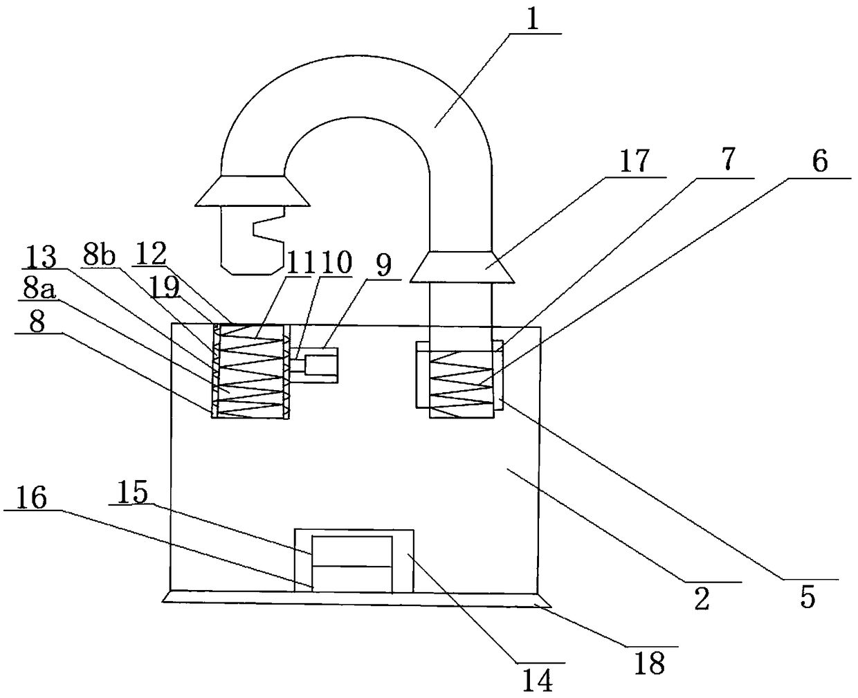
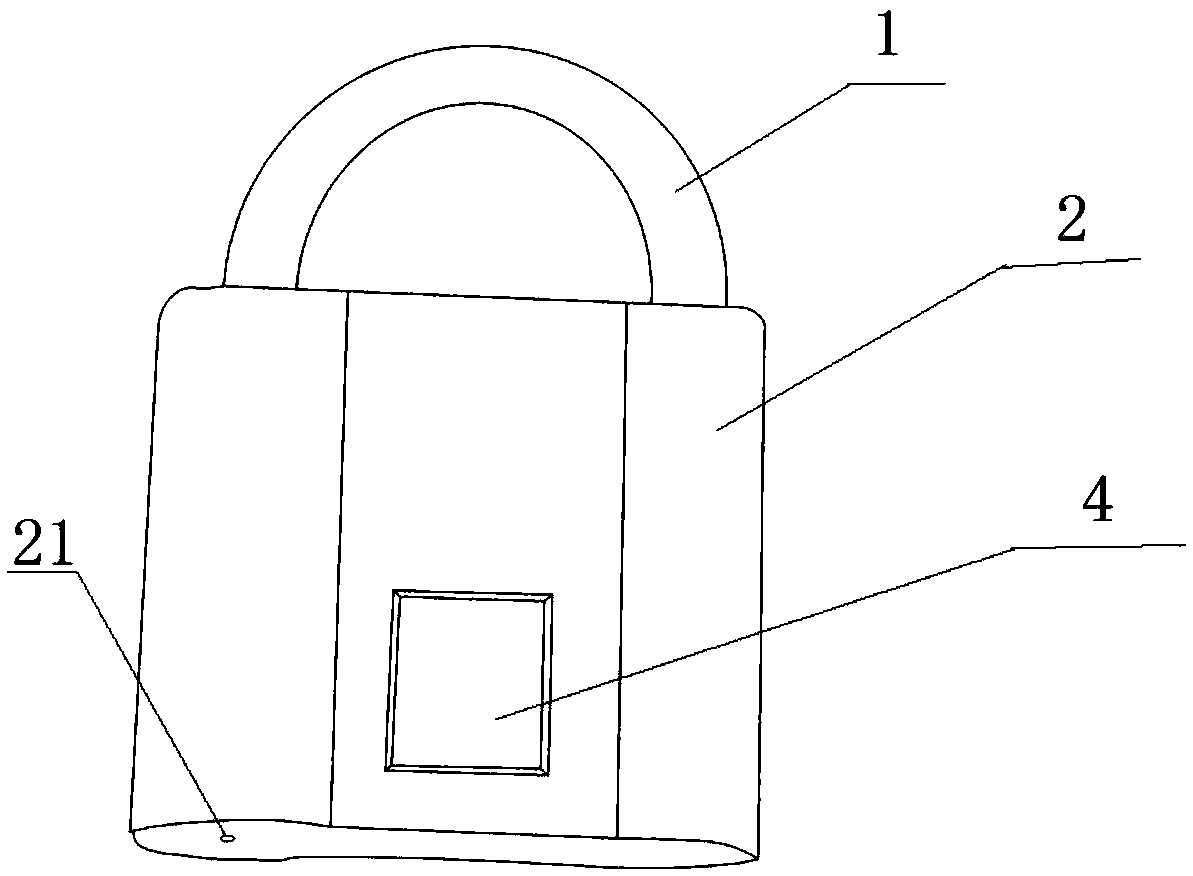
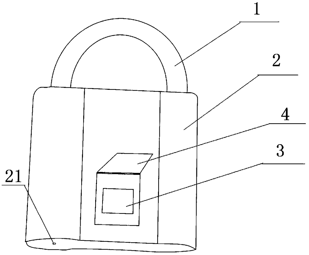
[0026] Such as Figure 1 to Figure 3 As shown, the high-efficiency antifreeze fingerprint padlock device includes a lock ear 1 and a lock body 2, and the middle part of the lock body 2 surface is provided with a fingerprint reader 3, and the fingerprint reader 3 is fixedly installed with the fingerprint reader 3 A fingerprint reader cap 4 matching in size is provided with a resistance wire 13 on the back of the fingerprint reader 3; a first groove 5 is provided on the right side of the upper surface of the lock body 2, and the bottom of the first groove 5 A first spring 6 is fixedly connected, and the top of the first spring 6 is fixedly connected to the lock ear 1 , and the right side of the surface of the lock ear 1 is provided with a first card groove 7 matching the first groove 5 The left side of the upper surface of the lock body 2 is provided with two nested second grooves 8 equal in depth, the inner second groove 8 is the second groove A8a, and the second groove A8a is ...
Embodiment 2
[0029] Such as Figure 1 to Figure 3As shown, the difference between this embodiment and Embodiment 1 is that a trumpet-shaped waterproof cover 17 is sleeved at the connection between the lock lug 1 and the two ends of the lock body 2, and the bottom surface of the lock body 2 is fixedly connected with a Trumpet-shaped waterproof cover 18, the waterproof cover 17 and waterproof cover 18 are all made of rubber, which can better avoid the contact between the lock lug of the fingerprint padlock and the lock body, and the bottom surface of the lock body to be exposed to rain and snow and cause rust and icing; the lock body 2 adopts copper heat insulation material, which plays the role of heat preservation, so that the fingerprint padlock can be kept free from icing in severe cold weather. The diameter of the small hole 21 is 0.2-0.5mm, which ensures that the liquid water can be discharged out of the lock body 2 smoothly, and at the same time, the diameter of the small hole 21 prev...
PUM
| Property | Measurement | Unit |
|---|---|---|
| Diameter | aaaaa | aaaaa |
Abstract
Description
Claims
Application Information