Differential pressure wind meter

a wind meter and differential technology, applied in the direction of volume metering, electric generator control, instruments, etc., can solve the problems of inconvenient and fast response, inability to accurately measure wind velocity and direction, and high cost, so as to improve wind velocity and direction measurement, simple and scalable design, durability and longevity

Inactive Publication Date: 2006-08-22
COREY FRANCIS SCOTT +1
View PDF10 Cites 11 Cited by
  • Summary
  • Abstract
  • Description
  • Claims
  • Application Information

AI Technical Summary

Benefits of technology

[0017]A further object of the present invention is to provide an improved apparatus that provides an instantaneous measurement of wind direction.
[0018]Another object of the present invention is to provide an improved apparatus that possesses angled, outwardly extending ports to prevent sensor fouling.
[0021]A further object of the present invention is to provide an improved apparatus that prevents ice accumulation via the use of strategically located heating elements.
[0022]Yet another object of the present invention is to provide an improved apparatus that possesses a multi-lobed overhead cover / roof structure that does not impede / influence the movement of the wind as its passes the apparatus, and yet which protects an array of internal sensors.
[0024]Another object of the present invention is to provide an improved wind velocity and direction measuring apparatus that includes no moving parts, and which possesses a simple and scalable design which can be fabricated of lightweight inexpensive materials and devices which provide a commensurate degree of economy, durability and longevity.
[0025]According to the present invention, the above-described and other objects are accomplished by a wind meter comprising a plurality of micro-electro-mechanical (MEM) differential pressure sensors positioned in an even number of circumferential ports arranged in an equally-spaced, circular pattern on the exterior of a housing. The MEM sensors and other control system electronics are contained in the housing that is equipped with a cover / roof structure. The control system may utilize a wind velocity correction algorithm to correct for variations in ambient air density due to fluctuations in temperature, pressure, and / or humidity. The multi-lobed overhead cover / roof structure is configured and positioned above the ports such that it does not impede / influence the movement of the wind as it passes the present invention. The cover / roof structure also serves to prevent the ingress of moisture into the housing. A plurality of heating elements may be strategically located throughout the present invention to prevent ice accumulation. A plurality of tubular structures extend outwardly from the ports / MEM sensors to prevent any fouling of the sensors. The tubular structures include an internal coating of hydrophobic material and are oriented at a slight angle from the horizontal in order to accomplish this protection. The openings at the ends of the tubular structures are positioned outside the fluid boundary layer. The present invention contains no moving parts due to its entirely solid state construction. The present invention is fabricated of lightweight materials / devices chosen to provide an appropriate degree of durability / longevity. The present invention possesses a simple, yet scalable, design that may be economically manufactured and sold to provide for widespread use.

Problems solved by technology

(1) Rotating, mechanical devices that typically have either a set of three cups or a propeller that rotates at a speed proportional to the wind velocity. The rotation of the cups / propeller is then converted to electrical signals either in the form of pulses or a voltage. However, due to the mechanical nature of such devices, light wind conditions might not overcome the frictional component of the device. The result may be an increasingly incorrect and sluggish response to quickly changing conditions. Furthermore, the device can easily fail in severe weather conditions such as icing or snow.
(2) Acoustic or Doppler anemometers. These devices measure the speed or frequency of a pressure pulse and rely on the variation in the speed of sound as a function of wind speed. While they can measure the wind velocity in all three dimensions simultaneously, they are expensive, sensitive to environmental shock (e.g. loud noises such as gun shots), and extremely sensitive to the effects of ice accumulation.
(3) Hot-wire anemometers. These devices operate on the principle that wind passing over a heated wire will cool that wire by an amount that is proportional to wind velocity. As the wind speed increases, increased current flow is needed to maintain the wire at a given temperature. In and of themselves these devices are incapable of measuring wind direction, and they generally result in excessive power consumption.
(4) Differential pressure sensors such as pitot or pressure tubes. In these devices, the differential between upstream and downstream pressures is measured by a differential pressure transducer. Generally, the pressure differential is quite small, as is the resulting output signal.
Unfortunately, none of the foregoing prior art patents suggest a MEMS-based differential pressure sensing technology capable of measuring both wind velocity and direction.
Moreover, the prior art does not provide for the protection of the sensors by any means that will not impede / influence the movement of the wind as its passes the sensors.

Method used


Image

  • Differential pressure wind meter
  • Differential pressure wind meter
  • Differential pressure wind meter

Examples


Embodiment Construction

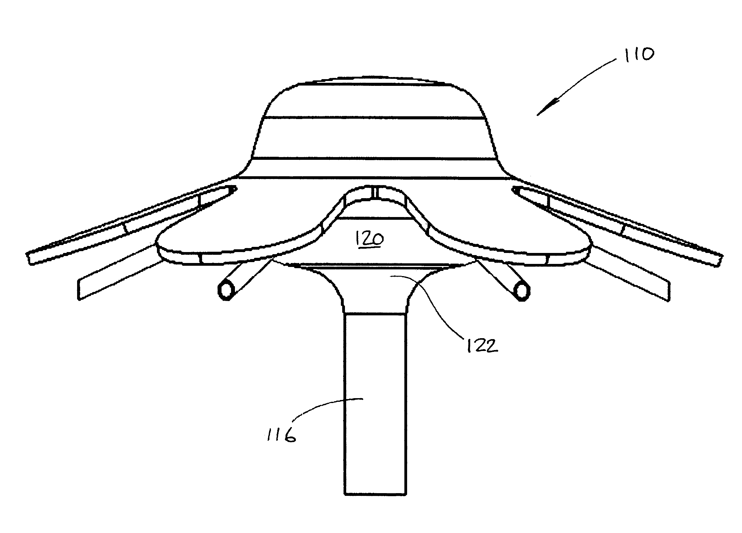
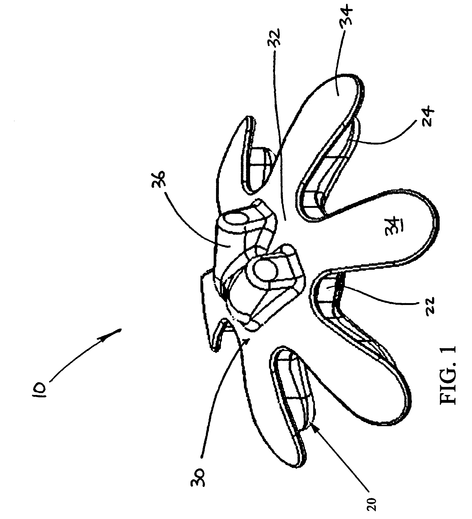
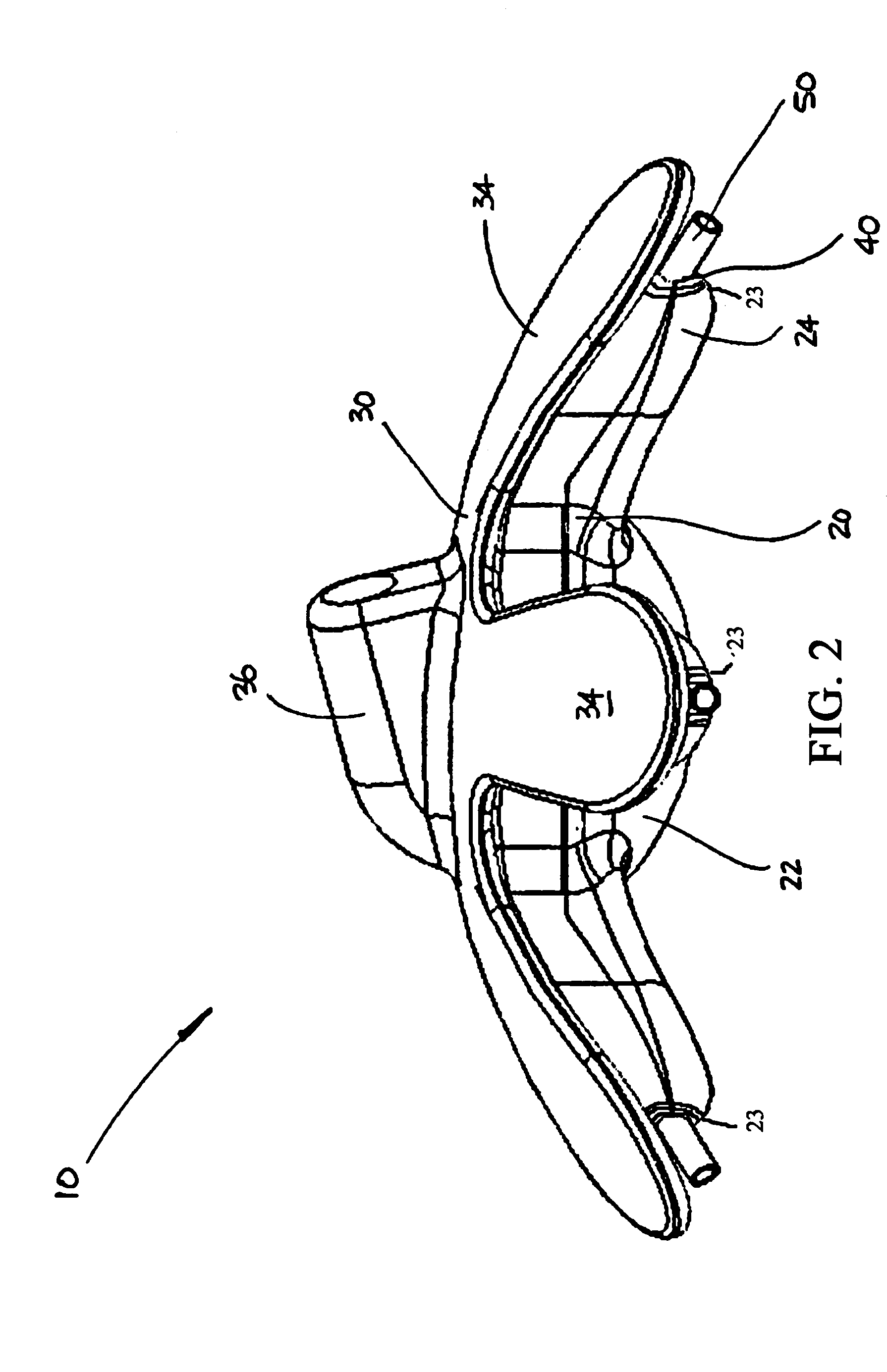
[0034]FIGS. 1–3 are, respectively, top, side, and bottom perspective views of a wind meter 10 according to a preferred embodiment of the present invention. The wind meter 10 preferably comprises a housing 20, a cover / roof structure 30, a plurality of ports 40, a plurality of tubular structures 50, a plurality of MEM differential pressure sensors 60, and a control system 70.

[0035]The housing 20 generally comprises a central section 22 formed with an even number of outwardly extending lobes 24. The central section 22 and lobes 24 are preferably fabricated as a unitary component from a commercially available, injection moldable plastic such as injected PVC, ABS or polycarbonate. However, any strong, lightweight material, such as other plastic material or metal (e.g. aluminum) will suffice, so long as it can be formed into the shape of the housing 20 of the present invention.

[0036]The cover / roof structure 30 is preferably fixedly attached to the housing 20 and generally comprises a cent...


PUM


Abstract

A wind meter comprising a plurality of micro-electro-mechanical (MEM) differential pressure sensors positioned in a lobed housing, with an even number of circumferential ports arranged in an equally-spaced, circular pattern at the distal ends of the lobes of the housing, with tubes leading inward from the ports to the MEM sensors. The MEM sensors and other control system electronics are contained in the housing and are fully enclosed therein. The lobed housing structure does not impede or influence the movement of the wind as it passes and yet serves to prevent the ingress of moisture into the housing, thereby preventing fouling of the sensors. The tubular structures include an internal coating of hydrophobic material and are oriented at a slight angle from the horizontal in order to accomplish this protection. The openings at the ends of the tubular structures are positioned outside the fluid boundary layer.

Description

CROSS-REFERENCE TO RELATED APPLICATIONS[0001]The present application derives priority from U.S. Provisional Patent Application Ser. No. 60 / 471,394 filed May 19, 2003.BACKGROUND OF THE INVENTION[0002]1. Field of the invention[0003]The present invention relates to devices for fluid flow measurement and, more particularly, to apparatus for determining wind speed / velocity and direction utilizing a plurality of MEMS differential pressure sensors.[0004]2. Description of the Background[0005]There are many existing devices that attempt to determine the direction and velocity of wind. The various approaches taken to date have met with varying degrees of success. While such devices may incorporate any one of a variety of sensing technologies, they may be generally categorized as follows:[0006](1) Rotating, mechanical devices that typically have either a set of three cups or a propeller that rotates at a speed proportional to the wind velocity. The rotation of the cups / propeller is then conver...

Claims


Application Information

Patent Timeline
Patent Type & Authority Patents(United States)
IPC IPC(8): G01P5/00H02P9/04
CPCG01P13/02G01P5/14
Inventor COREY, FRANCIS SCOTTLANE, BEN
Owner COREY FRANCIS SCOTT
Why Eureka
Try Eureka