Leading edge ice-protection system

Active Publication Date: 2018-06-21
AIRBUS OPERATIONS GMBH
View PDF0 Cites 11 Cited by
  • Summary
  • Abstract
  • Description
  • Claims
  • Application Information

AI Technical Summary

Benefits of technology

[0007]In view of the above it can be considered an object of the present technology to provide a less complex and lighte

Problems solved by technology

For an aircraft, structures such as the wing and its high-light devices, horizontal and vertical tail planes, propellers, engine intakes, are prone to icing.
This is undesirable when in use because the ice destroys the smooth flow of air over the structure, therefore decreasing the ability of the airfoil to perform its intended function and also increases drag and weight of the aircraft.
If a buildup of ice is not prevented or removed from these surfaces, then the ice can lead to the degradation of the aerodynamic performance of the structure.
The ice may also lead to a significant weight increase to the aircraft or potentially block an intake to an engine.
Such arrangements are commonly used in large passenger aircraft but they have their disadvantages.
The piping used to route the bleed air as a result is made of high performance metallic alloys such as titanium, which increases the cost.

Method used


Image

  • Leading edge ice-protection system
  • Leading edge ice-protection system
  • Leading edge ice-protection system

Examples


Embodiment Construction

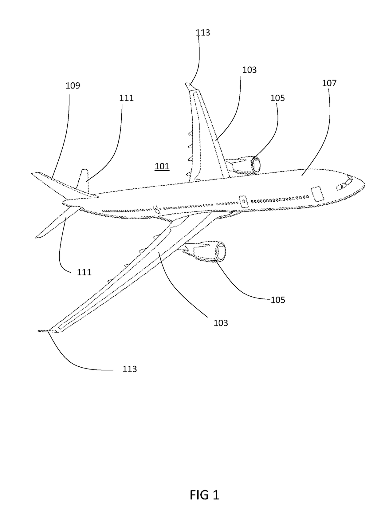
[0020]With reference to FIG. 1, an aircraft 101 comprises a pair of aerodynamic structures in the form of wings 103 that join into a fuselage 107. Each wing 103 comprises a leading edge and a trailing edge bounded by an upper wing surface and lower wing surface. Such aerodynamic structures are configured to generate a lift force by creating a pressure differential between the upper surface (low pressure) and lower surface (high pressure) when subjected to an aerodynamic flow.

[0021]Each wing 103 carries an engine 105 that is mounted using a wing to engine pylon. The aircraft 101 comprises further lifting surface assemblies in the form a horizontal tail plane 111 and a vertical tail plane 109, each attached at the rear of the fuselage 107.

[0022]The aircraft 101 further comprises a set of wing tip devices 113, which are each attached at a distal end of a wing 103.

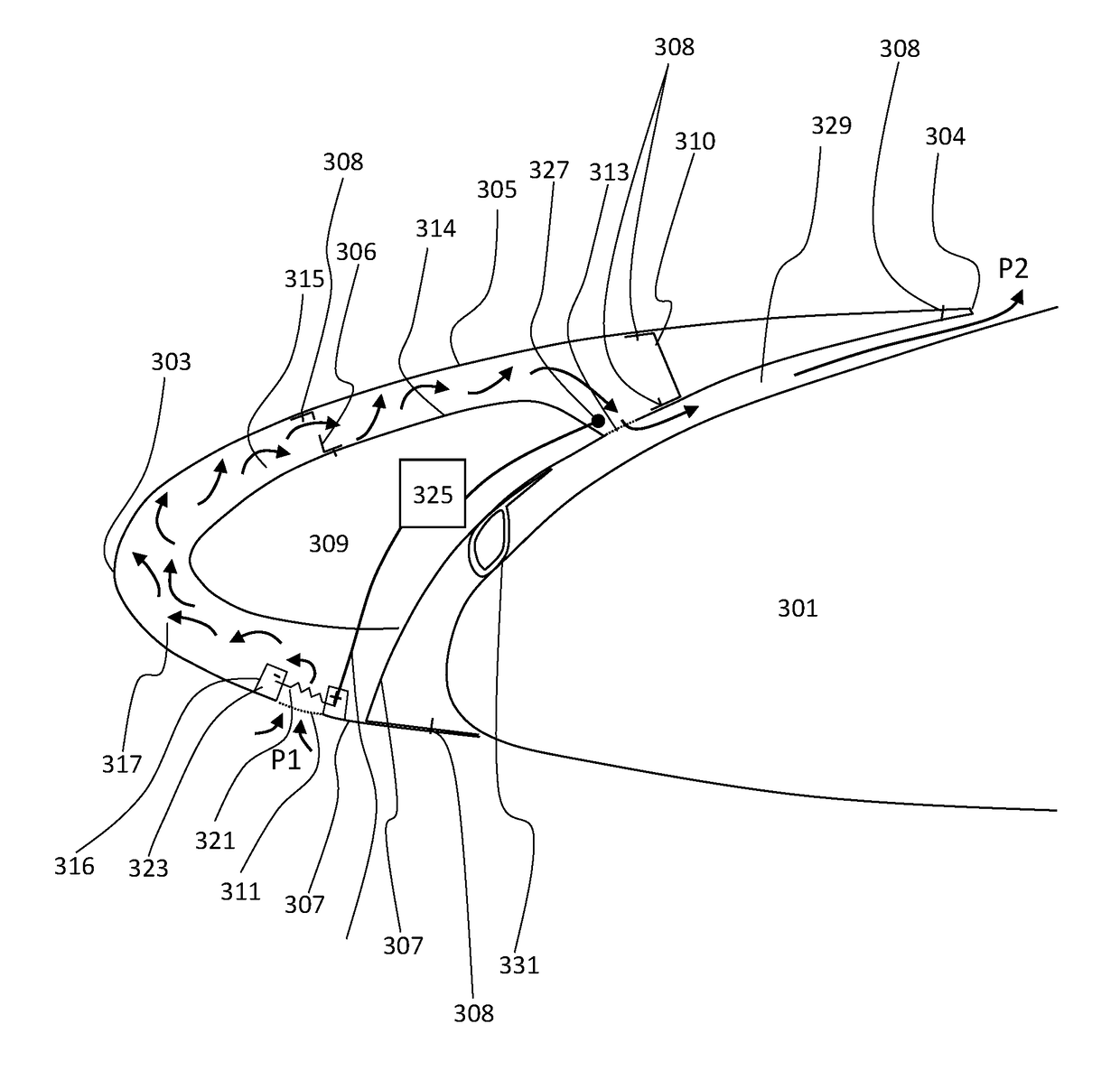
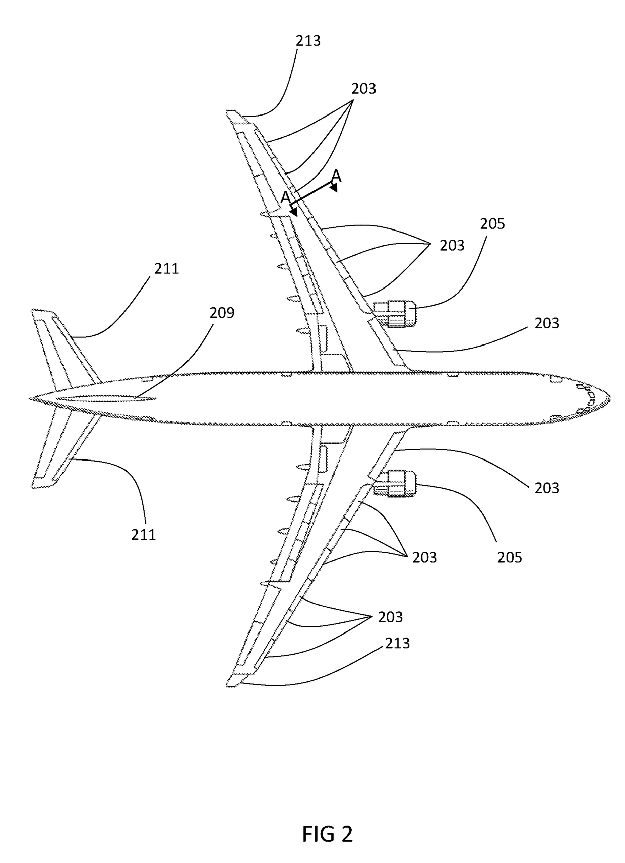
[0023]With reference to FIG. 2, each wing comprises a set of high-lift devices called leading edge slats 203 which are mecha...


PUM


Abstract

An ice-protection system for an aerodynamic structure for an aircraft comprising: an outer skin defined by a leading edge point and a trailing edge point that are interconnected by an upper skin and a lower skin, an internal chamber defined within the outer skin configured to be in fluid communication with the atmosphere external to the outer skin via an inlet and an outlet, and at least one air heater provided within the chamber in proximity to the inlet, wherein during use, a pressure differential exists between the inlet and the outlet that causes external air to flow through the chamber from the inlet to the outlet, and wherein the heater is configured to heat the air passing through the inlet such that the temperature of the air in the chamber is sufficiently increased so as to prevent ice accretion on the outer skin.

Description

CROSS-REFERENCES TO RELATED APPLICATIONS[0001]This application claims the benefit of the German patent application No. 10 2016 125 026.0 filed on Dec. 20, 2016, the entire disclosures of which are incorporated herein by way of reference.FIELD OF TECHNOLOGY[0002]The present technology relates to an ice-protection system suitable for an aerodynamic structure of an aircraft.BACKGROUND OF THE INVENTION[0003]For an aircraft, structures such as the wing and its high-light devices, horizontal and vertical tail planes, propellers, engine intakes, are prone to icing. This is undesirable when in use because the ice destroys the smooth flow of air over the structure, therefore decreasing the ability of the airfoil to perform its intended function and also increases drag and weight of the aircraft. Aircraft certified for flight in icing conditions are therefore normally fitted with de-icing and anti-icing systems, which when required, are used to remove (“de-ice”) or prevent (“anti-ice) a build...

Claims


Application Information

Patent Timeline
IPC IPC(8): B64D15/04B64C21/02
CPCB64D15/04B64C21/02B64C2230/10B64C9/24B64C21/04B64D15/12Y02T50/10
Inventor LORENZ, FLORIAN
Owner AIRBUS OPERATIONS GMBH
Why Eureka
Try Eureka