Adjusting device for single-cylinder turbine

A technology of regulating devices and steam turbines, applied in mechanical equipment, engine components, machines/engines, etc., can solve the problems of large footprint, inconvenient maintenance, high equipment cost, etc., and achieve high safety, stable operation, and safety assurance effects

Inactive Publication Date: 2018-12-25
毛玲波
View PDF0 Cites 0 Cited by
  • Summary
  • Abstract
  • Description
  • Claims
  • Application Information

AI Technical Summary

Problems solved by technology

[0002] A steam turbine is a rotary power machine that converts steam energy into mechanical work, also known as a steam turbine. It is mainly used as a prime mover for power generation, and can also directly drive various pumps, fans, compressors and ship propellers. Use the exhaust gas or intermediate extraction of the steam turbine to meet the heating needs of production and life. According to the actual needs of the steam turbine, the steam turbine usually needs to be equipped with a regulating device to control the intake of the steam turbine. The traditional device for regulating the steam turbine is generally It uses hydraulic control, but to use hydraulic pressure to achieve the purpose of the control device, a large set of hydraulic equipment is required, which usually occupies a large area. Now there are also some equipment that use electronic control to adjust the air intake of the steam turbine. Through the sensor The combination with PLC achieves the purpose of precise control, but the cost of this kind of equipment is high and the maintenance is inconvenient

Method used


Image

  • Adjusting device for single-cylinder turbine
  • Adjusting device for single-cylinder turbine
  • Adjusting device for single-cylinder turbine

Examples


Embodiment Construction

[0018] All features disclosed in this specification, or steps in all methods or processes disclosed, may be combined in any manner, except for mutually exclusive features and / or steps.

[0019] Any feature disclosed in this specification, unless specifically stated, can be replaced by other alternative features that are equivalent or have similar purposes. That is, unless expressly stated otherwise, each feature is one example only of a series of equivalent or similar features.

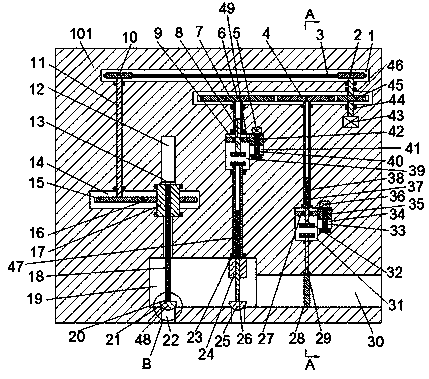
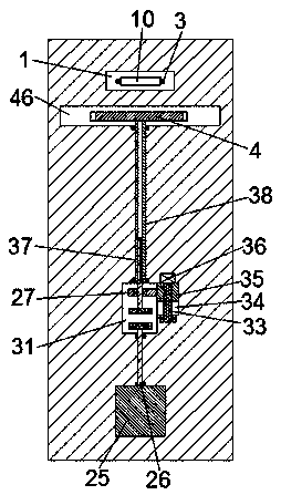
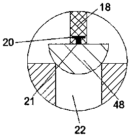
[0020] Such as Figure 1-3As shown, the device of the present invention is an adjusting device for a single-cylinder steam turbine, including a base body 101. A first cavity 1 extending left and right is arranged inside the base body 101, and a second cavity 1 is arranged below the right side of the first cavity 1. Cavity 46, the upper and lower end walls of the second cavity 46 are rotatably installed with a first rotating shaft 44 extending up and down through bearings, and the upper end of the fir...


PUM


Abstract

The invention discloses an adjusting device for a single-cylinder turbine. The adjusting device comprises a base body. A left-right-extending first cavity is formed in the base body. A second cavity is formed below the right side of the first cavity. The upper end wall and the lower end wall of the second cavity are rotationally provided with an up-down-extending first rotation shaft through bearings. The upper end of the first rotation shaft stretches into the first cavity and is fixedly connected with a first belt wheel. The lower end of the second cavity is provided with a rotation motor which is in power connection with the first rotation shaft. The left side in the first cavity is provided with a second belt wheel which is connected with the first belt wheel through a belt. A third cavity is formed below the left side of the first cavity. A second rotation shaft is rotationally arranged between the first cavity and the third cavity through a bearing. The upper end of the second rotation shaft stretches into the first cavity and is fixedly connected with the second belt wheel.

Description

technical field [0001] The invention relates to a regulating device for a single-cylinder steam turbine. Background technique [0002] A steam turbine is a rotary power machine that converts steam energy into mechanical work, also known as a steam turbine. It is mainly used as a prime mover for power generation, and can also directly drive various pumps, fans, compressors and ship propellers. Use the exhaust gas or intermediate extraction of the steam turbine to meet the heating needs of production and life. According to the actual needs of the steam turbine, the steam turbine usually needs to be equipped with a regulating device to control the intake of the steam turbine. The traditional device for regulating the steam turbine is generally It uses hydraulic control, but to use hydraulic pressure to achieve the purpose of the control device, a large set of hydraulic equipment is required, which usually occupies a large area. Now there are also some equipment that use electro...

Claims


Application Information

Patent Timeline
IPC IPC(8): F01D17/00F01D17/10
CPCF01D17/00F01D17/10
Inventor 毛玲波
Owner 毛玲波
Why Eureka
Try Eureka