Multi-linkage valve

A technology of multi-valve and valve main body, applied in the field of multi-valve, can solve the problems of increasing the volume of multi-valve, complex on-site installation, unreliability, etc. The effect of structural firmness

Pending Publication Date: 2018-12-25
深圳市德平国瀚汽车电子科技有限公司
View PDF1 Cites 1 Cited by
  • Summary
  • Abstract
  • Description
  • Claims
  • Application Information

AI Technical Summary

Problems solved by technology

[0002] The traditional electronically controlled air suspension pipeline system is generally composed of multiple joints, tees, pipelines and five independent two-position two-way solenoid valves. It has the following disadvantages: First, there are too many tees and joints, resulting in The installation is complicated and scattered, and it is particularly easy to cause air leakage and unreliability of the system; second, because the inflation and exhaust share the same pipeline and are controlled by a main solenoid valve, the system cannot be filled and exhausted at the same time. The principle of filling the rear row causes the air suspension system to fail to reflect load changes and dynamic adjustments in a timely manner; third, the internal pressure of the air spring cannot be measured, so when the air spring leaks, it cannot be monitored in time, which has a certain impact on the safety of the system
[0004] The above-mentioned existing technical solutions have the following defects: First, in the process of producing this type of multi-valve, it is necessary to individually weld the cables for each pressure sensor, and then lead the cables separately to the control circuit board Phase-to-phase electrical connection, this method that needs to be welded separately and externally connected to the control circuit board is relatively complicated, which is not conducive to production and installation, resulting in a significant increase in production costs and installation costs; The sensor will increase the volume of the entire multi-valve, which is not conducive to saving installation space

Method used


Image

  • Multi-linkage valve
  • Multi-linkage valve
  • Multi-linkage valve

Examples


Embodiment Construction

[0039] The present invention will be described in further detail below in conjunction with the accompanying drawings.

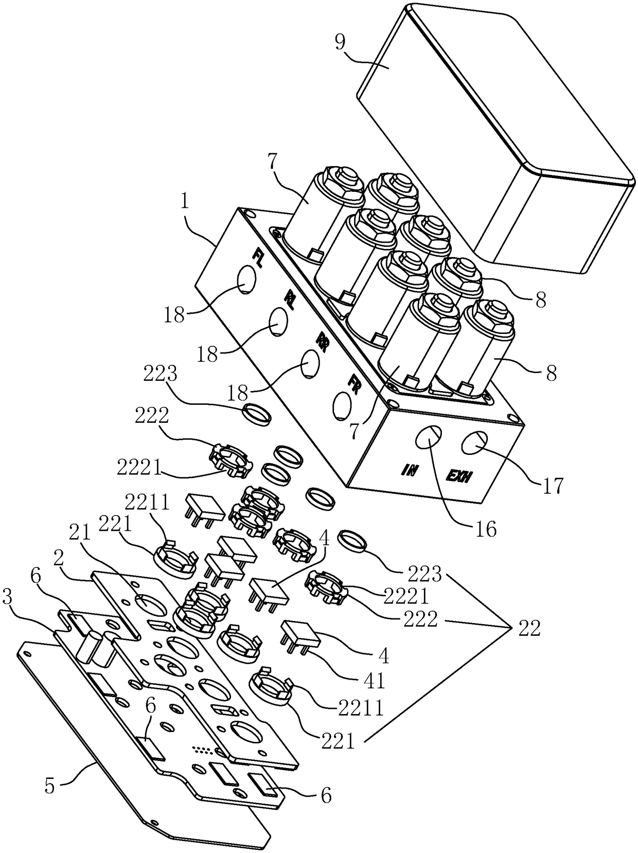
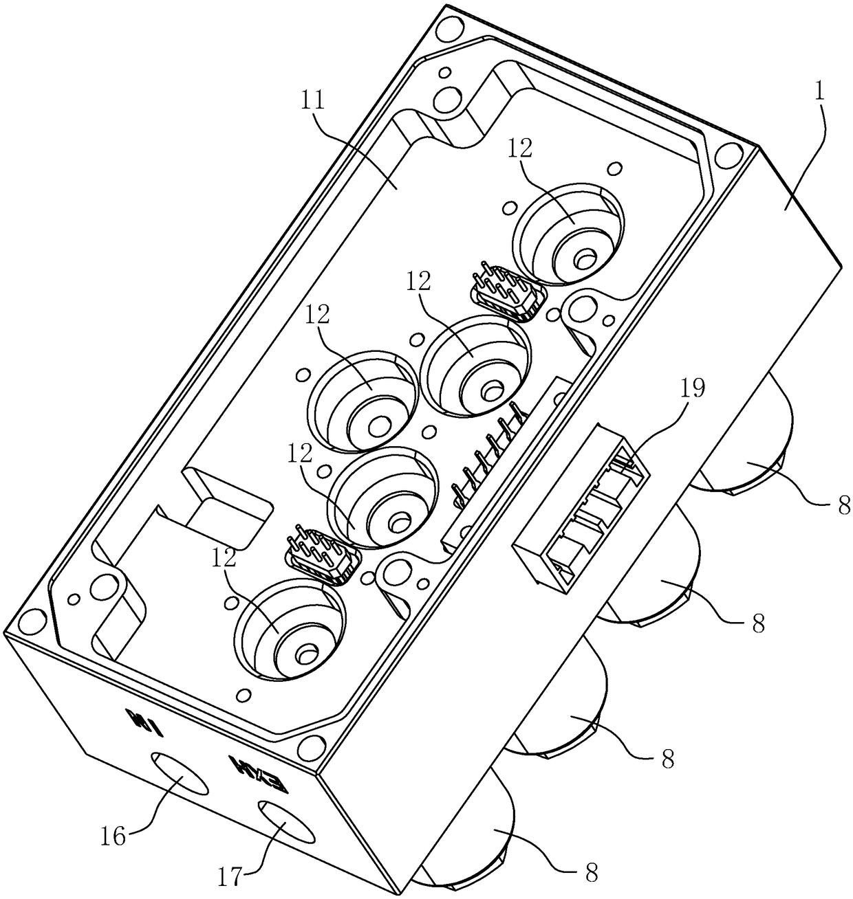
[0040] A manifold valve, combined with figure 1 with figure 2 As shown, it includes: valve main body 1, mounting plate 2, control circuit board 3, pressure sensor 4, cover plate 5, sponge pad 6, inlet solenoid valve 7, outlet solenoid valve 8 and protective cover 9.

[0041] The surface of the valve body 1 is provided with a concave cavity 11, and the bottom wall of the concave cavity 11 is provided with five counterbore holes 12. In other embodiments, the number of counterbore holes 12 can be increased or decreased adaptively, and can be two, three, or four. one, six or more; the mounting plate 2 is arranged in the concave cavity 11, the mounting plate 2 has a through hole 21, the mounting seat 22 is located on the mounting plate 2, and the positions and numbers of the mounting seat 22 and the through hole 21 are uniform. It is arranged corresponding to t...


PUM


Abstract

The invention relates to a multi-linkage valve. The multi-linkage valve comprises a valve body, an installing plate, a control circuit board, pressure sensors and a cover plate, a cavity is formed inthe surface of the valve body, and multiple counter bored holes are formed in the bottom wall of the cavity; the installing plate is located inside the cavity and provided with through holes and installing bases, the installing bases and the through holes correspond to the counter bored holes in position and number, and the installing bases are inserted into the counter bored holes; the control circuit board is located in the cavity and gets away one side of the bottom wall of the cavity relative to the installing plate; the pressure sensors are installed inside the installing bases and electrically connected to the control circuit board through pins; the cover plate is used for sealing the cavity. The multi-linkage valve solves the problem that pressure sensors of a common linkage valve are arranged to protrude, and as a result the size is too large; the pressure sensors are arranged inside the valve body to be directly connected with the control circuit board electrically, and therefore the multi-linkage valve has the advantages of being low in production cost and small in size.

Description

technical field [0001] The invention relates to the technical field of pipeline systems of electronically controlled air suspensions of vehicles, in particular to a multi-valve. Background technique [0002] The traditional electronically controlled air suspension pipeline system is generally composed of multiple joints, tees, pipelines and five independent two-position two-way solenoid valves. It has the following disadvantages: First, there are too many tees and joints, resulting in The installation is complicated and scattered, and it is particularly easy to cause air leakage and unreliability of the system; second, because the inflation and exhaust share the same pipeline and are controlled by a main solenoid valve, the system cannot be filled and exhausted at the same time. The principle of filling the rear row causes the air suspension system to fail to reflect load changes and dynamic adjustments in a timely manner; third, the internal pressure of the air spring canno...

Claims


Application Information

Patent Timeline
Patent Type & Authority Applications(China)
IPC IPC(8): F15B13/02
CPCF15B13/02
Inventor 肖国韩洁黄学蓉国成远李明勇周镜明
Owner 深圳市德平国瀚汽车电子科技有限公司
Why Eureka
Try Eureka