Computer chassis

A computer and chassis technology, applied in the field of electronic equipment, can solve the problems of burnout of parts in the main chassis, inconvenient use, large space occupied by the cooling device, etc., and achieve the effect of saving electricity

Inactive Publication Date: 2018-12-25
合肥斯姆雷品牌管理有限公司
View PDF10 Cites 0 Cited by
  • Summary
  • Abstract
  • Description
  • Claims
  • Application Information

AI Technical Summary

Problems solved by technology

[0002] The existing computer case is troublesome to install and inconvenient to use. At the same time, in summer, some places without air conditioners often cause the parts in the main case to burn out. It can only be obs

Method used


Image

  • Computer chassis
  • Computer chassis
  • Computer chassis

Examples


Embodiment 1

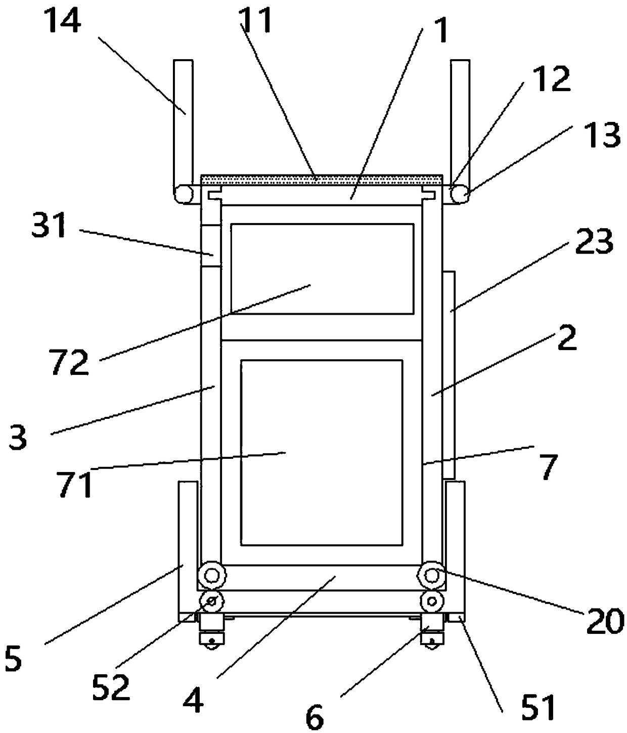
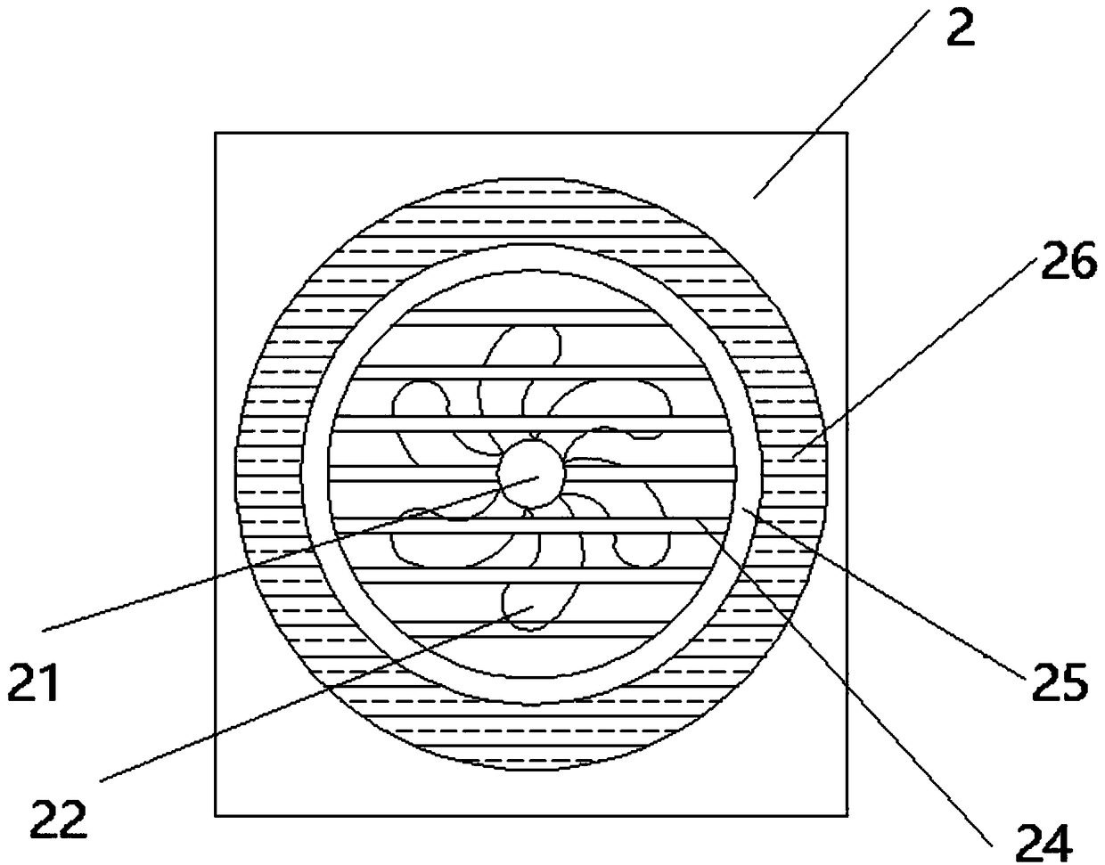
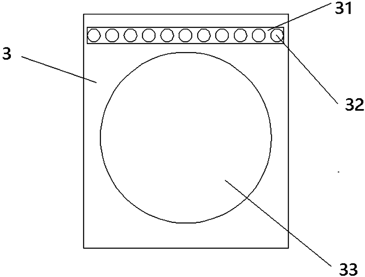
[0029] A kind of computer case, comprises top cover 1, right side plate 2, left side plate 3, base plate 4, base 5, folding wheel 6, panel 7 and back plate 8, as figure 1 As shown, the left and right ends of the bottom plate 4 are provided with side plate shafts 20, and the left side plate 3 and the right side plate 2 are rotationally connected with the bottom plate 4 through the side plate shafts 20, as image 3 As shown, the middle of the left side plate 3 is provided with an observation port 33, and the upper end of the left side plate 3 is provided with a lighting device 31, and the lighting device 31 is provided with some lighting lamps 32, such as figure 2 As shown, the heat dissipation motor 21 is provided in the middle of the right side plate 2, the inside of the heat dissipation electric motor 21 is provided with a protective net 24, the outer side of the heat dissipation motor is provided with a protective cover 23, the cooling motor 21 is fixed with fan blades 22, a...

Embodiment 2

[0031] The difference between this embodiment and embodiment 1 is that, as figure 2 As shown, a circle of heat absorbing device 26 is arranged on the outer side of the guardrail 25 .

[0032] The heat absorption device absorbs the heat in the host and converts it into electric energy for use by the cooling motor 21 .

Embodiment 3

[0034] The difference between this embodiment and embodiment 1 is that, as Figure 4 As shown, the limiting device includes a spring device 72 and a limiting block 71, the upper end of the base 4 is provided with a connecting column 75, the inner side of the connecting column 75 is fixedly connected to the spring device 72, and the inner side of the spring device 72 is fixedly connected to the limiting block 71.

[0035] During use, the main engine parts are placed in the middle of the limit block 71 for circuit installation, and the main engine parts can be fixed on the base plate 4 to a certain extent due to the force provided by the spring device 72 .


PUM


Abstract

A computer chassis Includes a top cover, a right panel, a left panel, a base plate, folding wheels, panels and backs. A lateral plate shaft is arranged at the left and right ends of the bottom plate,a left side plate and a right side plate are pivotally connected with a bottom plate through a side plate shaft, a heat dissipation motor is arranged in the middle of the right panel, a protective netis arranged on both sides of the heat dissipation motor, fan blades are fixed on the heat dissipation motor, a protective fence is arranged around the protective net, an upper end of that left side plate and the right side plate are provide with a sliding groove, a slide block is arranged on both sides of the top cover, an upper end of that top cov is provided with a shock-proof plate, a front end of that bottom plate is fixedly connecte with the panel, a limit device is arranged in that middle of the bottom plate, a power supply interface is arranged above the right side of the bottom plate,a low end of that base plate is fixedly connected with a back plate, a pow plug is arranged on the outer side of the back plate, a base can be arranged on the low end of the base plate, a wheel shaftis arranged in the base plate, the wheel shaft is fixedly connected with a universal wheel, a fixing block is arranged on the lower end of the base plate, and a finite position plate is arranged in the middle of the lower end of the base plate. The device is convenient to install, has good heat dissipation effect, and protects the parts in the main box and the safety of users.

Description

technical field [0001] The invention relates to the technical field of electronic equipment, in particular to a computer case. Background technique [0002] The existing computer case is troublesome to install and inconvenient to use. At the same time, in summer, some places without air conditioners often cause the parts in the main case to burn out. It can be observed that such operation is not only loaded down with trivial details but also laborious, and the cooling device is housed in the computer case that also has, but because the cooling device takes up a large space in the case, it causes a burden on the contrary. Contents of the invention [0003] The technical problem solved by the present invention is to provide a computer case to solve the problems raised in the above-mentioned background technology. [0004] The technical problem solved by the present invention adopts following technical scheme to realize: [0005] A computer case, comprising a top cover, a r...

Claims


Application Information

Patent Timeline
IPC IPC(8): G06F1/18G06F1/20
CPCG06F1/181G06F1/183G06F1/20
Inventor 曹结宾
Owner 合肥斯姆雷品牌管理有限公司
Why Eureka
Try Eureka