A vehicle-mounted battery storage box of a new energy vehicle

A technology for new energy vehicles and on-board batteries, applied in the direction of batteries, secondary batteries, battery pack components, etc., can solve the problems of easily damaged waste batteries and boxes, difficult removal of batteries, and delayed battery replacement time, etc., to achieve Increased service life, convenient and quick battery replacement, and simple operation

Active Publication Date: 2018-12-25
宁波辰煜机械科技有限公司
View PDF2 Cites 3 Cited by
  • Summary
  • Abstract
  • Description
  • Claims
  • Application Information

AI Technical Summary

Problems solved by technology

[0003] However, the traditional battery replacement system for new energy vehicles needs to be replaced with a new battery when the battery is damaged or reaches a certain lifespan. Due to the heavy gravity of the battery itself, the internal battery installed in the box is not easy to take out. Some long-term fixed batteries After the buckle is damaged, it is impossible to quickly take the internal battery of the box, which delays the time for battery replacement. If you directly pry it open with a screwdriver, it is easy to damage the waste battery and the box. In view of this, the invention provides a new energy car battery storage box, which has the following characteristics:

Method used


Image

  • A vehicle-mounted battery storage box of a new energy vehicle
  • A vehicle-mounted battery storage box of a new energy vehicle
  • A vehicle-mounted battery storage box of a new energy vehicle

Examples


Embodiment Construction

[0026] In order to make the technical means, creative features, goals and effects achieved by the present invention easy to understand, the present invention will be further described below in conjunction with specific embodiments.

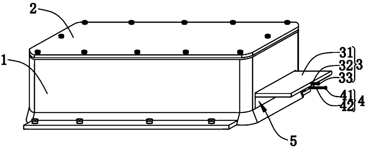
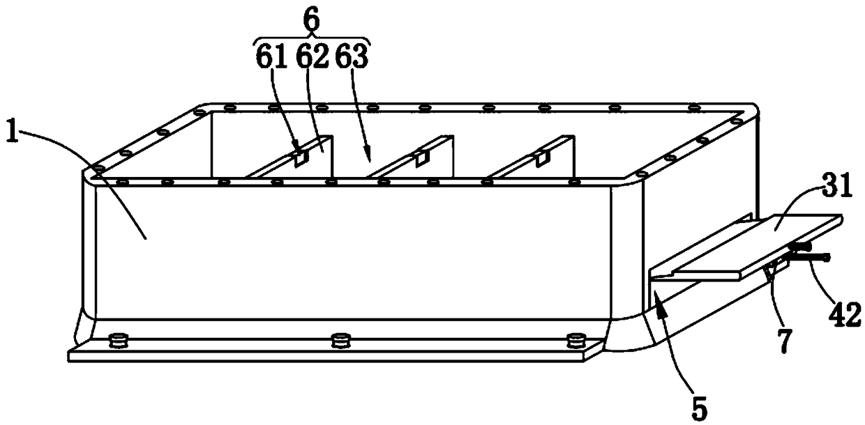
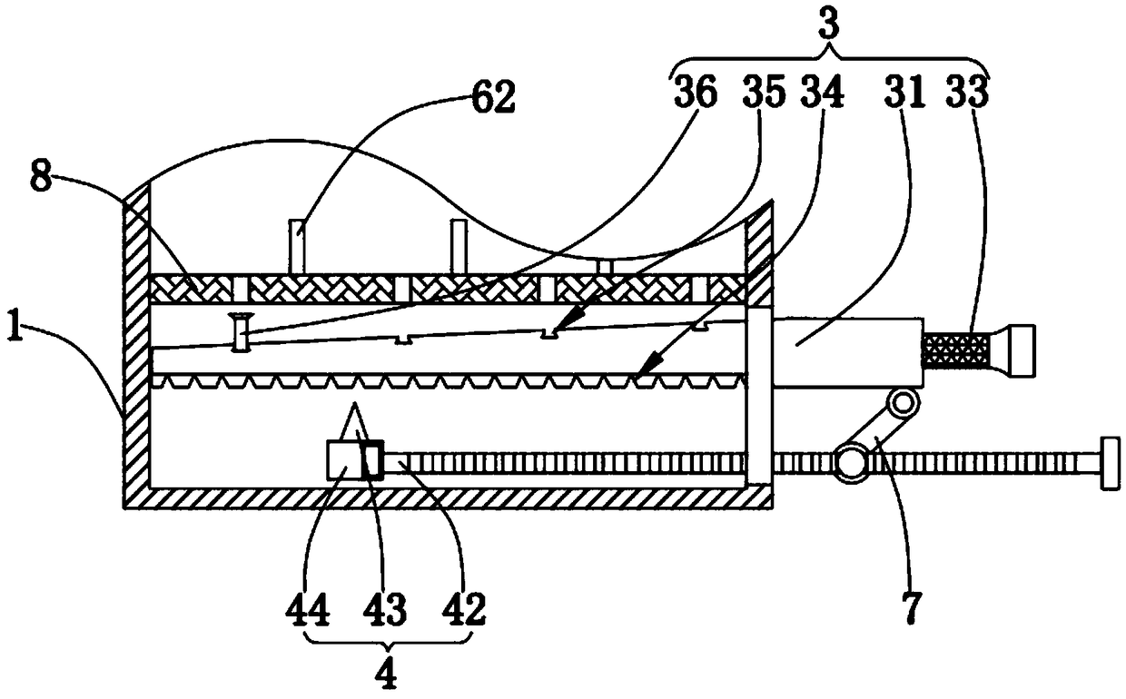
[0027] Such as figure 1 , figure 2 and Figure 5 As shown, a new energy vehicle vehicle battery storage box according to the present invention includes a box body 1, a cover plate 2, a disassembly mechanism 3, a support mechanism 4, a disassembly groove 5, a battery separation mechanism 6, a connection mechanism 7, and a battery storage box. Mechanism 8; the top of the hollow box 1 for placing the new energy vehicle battery is fixedly connected with the cover plate 2 of the cuboid structure for protecting the battery, and the inside of the hollow box 1 is fixedly connected with several The battery, the placement mechanism 8 for battery heat dissipation, the top of the placement mechanism 8 is equidistantly provided with the battery separation m...


PUM


Abstract

The invention relates to the battery field, in particular to a vehicle-mounted battery storage box of a new energy vehicle, comprising a box body, a cover plate, a disassembly mechanism, a support mechanism, a disassembly groove, a battery separation mechanism, a connection mechanism and a battery placement mechanism. The invention relates to the vehicle-mounted battery storage box of a new energyvehicle; two supporting plates are symmetrically fixed inside the box body; a filter screen is fixedly connected between the two supporting plates to support the battery and dissipate heat for the battery, thus prolonging the battery life; a plurality of top column grooves are equally formed in the surface of the filter screen to engage the top pillar inside any mounting groove in the surface ofa rocker. By rotating the screw rod, the position of the support base can be adjusted, limit teeth are engaged with clamping teeth, and the rocker can be jacked up by pressing a pressing column, so that the battery at the top of the top column corresponding to the top of the top column grooves is further jacked up, and the battery can be conveniently and quickly replaced; and an external eight-shaped taking groove is arranged at the edge of the side wall of each of a plurality of separators, so that the battery can be conveniently taken out after the battery is jacked up.

Description

technical field [0001] The invention relates to the field of batteries, in particular to a new energy vehicle vehicle battery storage box. Background technique [0002] New energy vehicles include pure electric vehicles, extended-range electric vehicles, hybrid vehicles, fuel cell electric vehicles, hydrogen engine vehicles, and other new energy vehicles. A device that can convert chemical energy into electrical energy in a part of the space of a container or composite container. It has positive pole and negative pole. [0003] However, the traditional battery replacement system for new energy vehicles needs to be replaced with a new battery when the battery is damaged or reaches a certain lifespan. Due to the heavy gravity of the battery itself, the internal battery installed in the box is not easy to take out. Some long-term fixed batteries After the buckle is damaged, it is impossible to quickly take the internal battery of the box, which delays the time for battery rep...

Claims


Application Information

Patent Timeline
Patent Type & Authority Applications(China)
IPC IPC(8): H01M2/10H01M10/613H01M10/625H01M10/6551H01M50/249
CPCH01M10/613H01M10/625H01M10/6551H01M2220/20H01M50/20Y02E60/10
Inventor 阮忠诚
Owner 宁波辰煜机械科技有限公司
Why Eureka
Try Eureka