A tape device and a mounting device thereof

A feeding device and equipment technology, applied in the direction of assembling printed circuits with electrical components, electrical components, printed circuit manufacturing, etc., can solve the problems of unqualified products, easy to drop dust or impurities, etc., and achieve the effect of a wide range of applications

Pending Publication Date: 2018-12-25
SHENZHEN BORWIN PRECISION MACHINERY
View PDF0 Cites 3 Cited by
  • Summary
  • Abstract
  • Description
  • Claims
  • Application Information

AI Technical Summary

Problems solved by technology

[0005] However, the existing placement machines are all top-to-bottom placement machines. When the products required to be placed are placed upwards, dust or impurities are easy to fall from the placement position, resulting in unqualified products. question

Method used


Image

  • A tape device and a mounting device thereof
  • A tape device and a mounting device thereof
  • A tape device and a mounting device thereof

Examples


Embodiment Construction

[0040] In order to make the object, technical solution and advantages of the present invention clearer, the present invention will be further described in detail below in conjunction with the accompanying drawings and embodiments. It should be understood that the specific embodiments described here are only used to explain the present invention, not to limit the present invention.

[0041] In describing the present invention, it should be understood that the terms "length", "width", "upper", "lower", "front", "rear", "left", "right", "vertical", The orientation or positional relationship indicated by "horizontal", "top", "bottom", "inner", "outer", etc. are based on the orientation or positional relationship shown in the drawings, and are only for the convenience of describing the present invention and simplifying the description, rather than Nothing indicating or implying that a referenced device or element must have a particular orientation, be constructed, and operate in a ...


PUM


Abstract

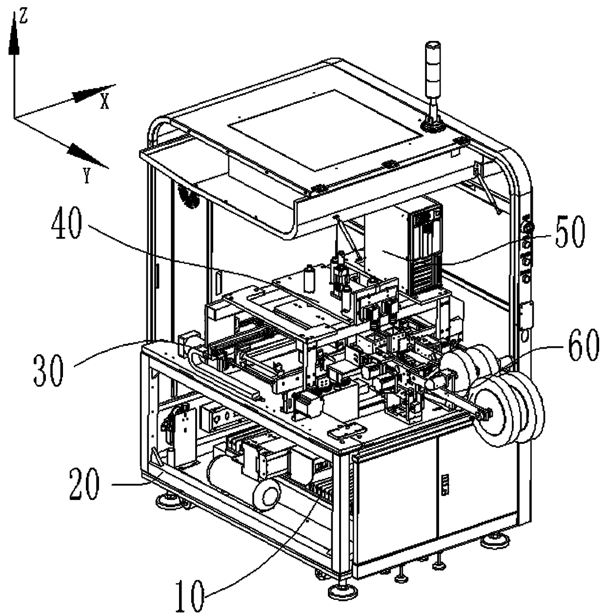
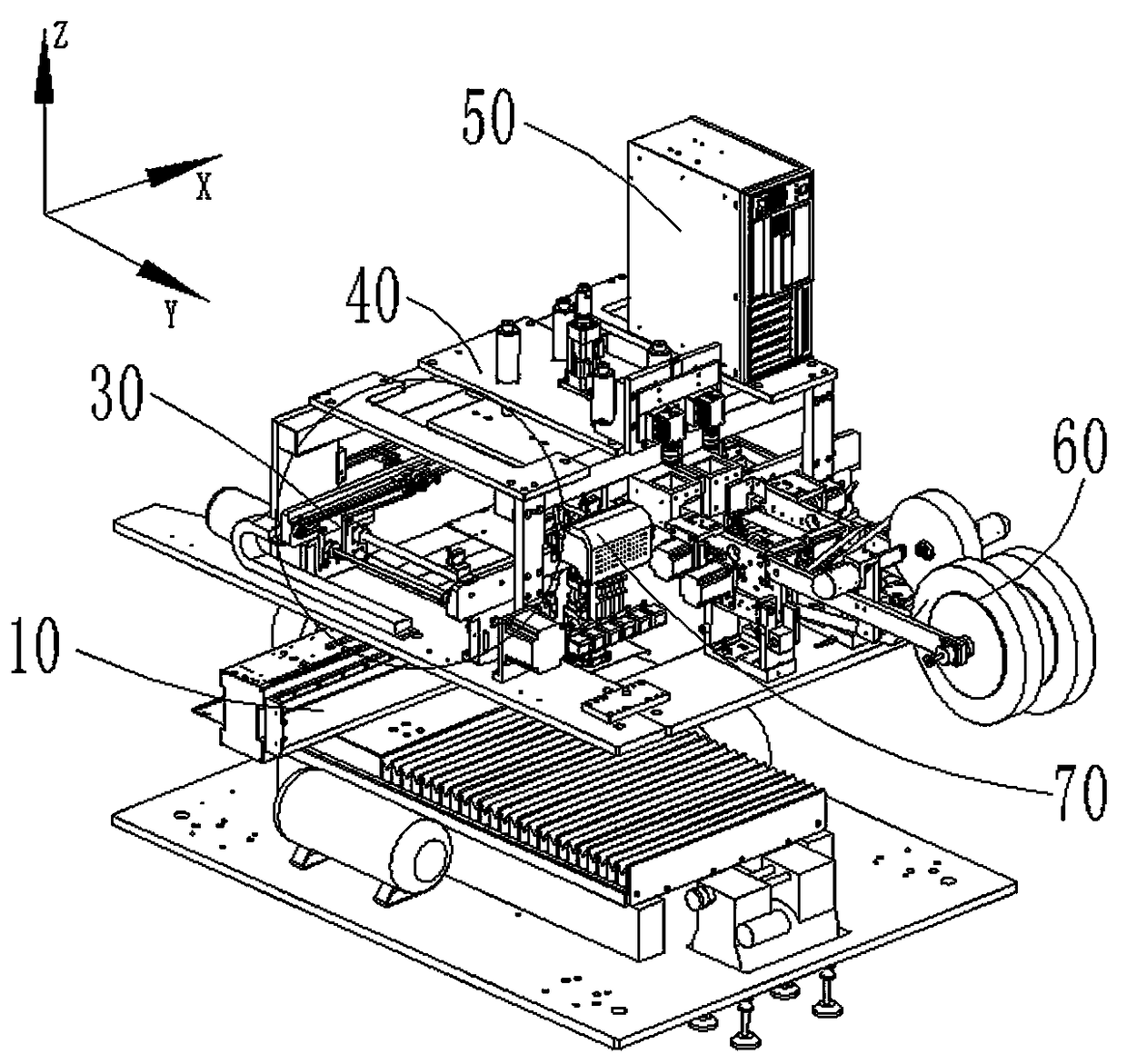
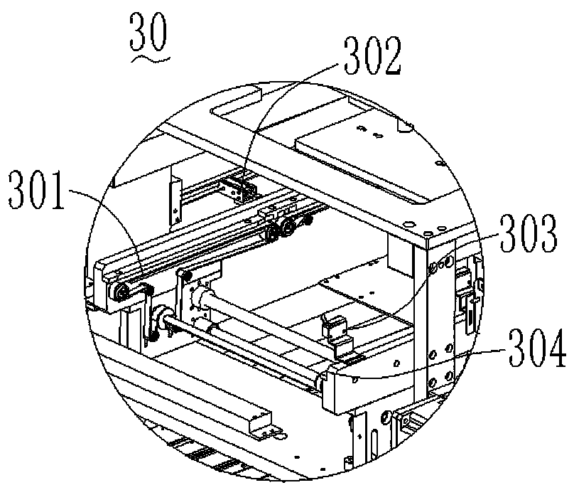
The invention relates to a tape device and a mounting device thereof. The tape device comprises a material stripping mechanism and a turnover bracket for mounting the material stripping mechanism, wherein the turnover bracket is rotatably connected with a shaft of the material stripping mechanism. By adding the turnover bracket, the stripping mechanism can realize 180-degree turning, that is, theconventional top-down mounting machine can be satisfied, and the purpose of mounting in different directions can also be satisfied, so that the application range of the stripping structure is wider; the mounting device comprises a mounting device, a feeding device, and the tape device, wherein the tape device, the mounting device and the feeding device are mounted and fixed on the mounting bracket. The method adopts a bottom-to-top mounting mechanism to carry out the mounting, and solves the problem that dust or impurities are easily dropped on the products required to be mounted by the conventional top-to-bottom mounting machine.

Description

technical field [0001] The invention relates to the field of chip technology, and relates to a material tape device and a mounting device thereof. Background technique [0002] In recent years, the structure of electronic tags consists of electronic tag chips, antennas, substrates, and outer packaging materials for labels. At present, flip chip (Flip Chip) technology is generally used to mount the chip on the antenna to make an Inlay, and then through Secondary encapsulation is made into an electronic label or a radio frequency smart card. Due to the complex processing technology for mounting the chip on the antenna, the production efficiency is low, and there are great hidden dangers in product quality. [0003] For printed board assembly manufacturers, in order to win in the fierce competition, the most important thing is to maximize the efficiency of the production line and increase the output of qualified products. However, to achieve this goal, it will inevitably be a...

Claims


Application Information

Patent Timeline
Patent Type & Authority Applications(China)
IPC IPC(8): H05K3/30
CPCH05K3/303
Inventor 李军强谢宏伟黄定亮纪磊
Owner SHENZHEN BORWIN PRECISION MACHINERY
Why Eureka
Try Eureka