

Stirring device for concrete block brick machine
A technology for concrete blocks and mixing devices, which is applied in the direction of cement mixing devices, clay preparation devices, cleaning methods and appliances, etc. It can solve the problems of uneven mixing of mixing materials and non-mixing of mixing materials, and achieve the reduction of rotation resistance and mixing materials. The effect of mixing evenly and being easy to rotate
Inactive Publication Date: 2018-12-28
湖州德海新型建材有限公司
View PDF0 Cites 4 Cited by
- Summary
- Abstract
- Description
- Claims
- Application Information
AI Technical Summary
Problems solved by technology
Since the stirring rod and the stirring scraper swing left and right to stir the material, the track is a sector with the length of the stirring rod as the radius, and because the cross-sectional shape of the mixing bucket is generally rectangular, when the stirring rod and the stirring scraper swing left and right to stir the material, There is a situation that the mixing material is not stirred at the corner of the mixing tank, so that the mixing device of the existing concrete block brick machine has the problem of uneven mixing of the mixing material
Therefore, the existing concrete block brick machine has the problem of uneven mixing of materials
Method used
View moreImage
Smart ImageViewing Examples

Examples
Embodiment Construction
Login to View More PUM
 Abstract
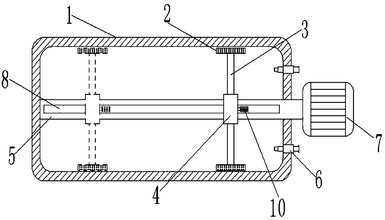
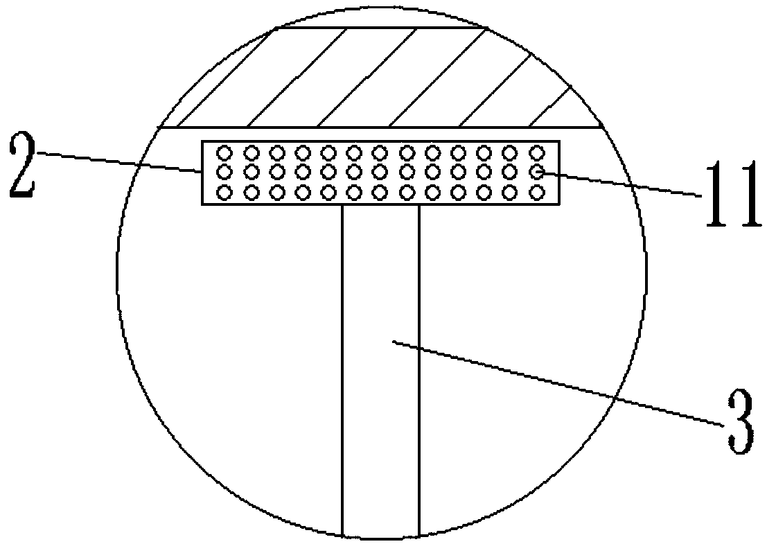
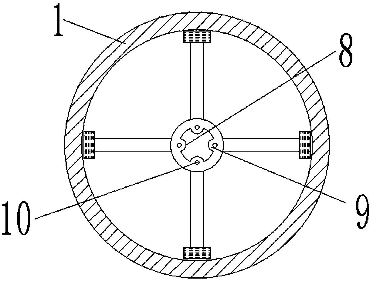
The invention discloses a stirring device for a concrete block brick machine. The stirring device for the concrete block brick machine comprises a stirring barrel (1), wherein a rotating rod (5) is arranged in the stirring barrel (1), a rotating motor (7) is arranged at one end of the rotating rod (5), a plurality of grooves (8) are formed in the rotating rod (5), and stirring rings (4) are connected on the periphery of the rotating rod (5) through the grooves (8); a plurality of bulges (9) which are glidingly connected with the grooves (8) are arranged on the inner circumference of the stirring rings (4), a plurality of stirring rods (3) are arranged on the outer circumference of the stirring rings (4), a stirring scraping plate (2) is arranged at one end, away from the circle center of each stirring ring (4), of each stirring rod (3), and a plurality of through holes (11) are formed in all the stirring scraping plates (2); linear motors (10) are arranged on all the bulges (9). The stirring device for the concrete block brick machine disclosed by the invention has the advantage of relatively uniform stirring of stirred materials.
Description
technical field The invention relates to the technical field of concrete block brick machine mixing, in particular to a mixing device for a concrete block brick machine. Background technique The mixing device of the concrete block brick machine is used to mix the materials for making concrete block bricks. The mixing device of the existing concrete block brick machine generally uses an eccentric wheel mechanism to make the stirring rod and the stirring scraper swing left and right, and one end of the stirring rod is arranged on the eccentric wheel mechanism, and the other end of the stirring rod is provided with a stirring scraper. The plate fits with the inner wall of the mixing bucket, and the shape of the mixing scraper also matches the shape of the corner of the mixing bucket. Since the stirring rod and the stirring scraper swing left and right to stir the material, the track is a sector with the length of the stirring rod as the radius, and because the cross-sectional...
Claims
Login to View More Application Information
Patent Timeline
 IPC IPC(8): B28C5/14B08B9/093
CPCB28C5/148B08B9/093B28C5/0806B28C5/0831
Inventor陈伟星
Owner湖州德海新型建材有限公司