
Glue jet drive mechanism

A driving mechanism and injection technology, applied in the field of injection molding machines, can solve the problems of complex structure of injection driving mechanism, and achieve the effect of simplifying the structure, solving the complex structure and improving the transmission accuracy.

Inactive Publication Date: 2018-12-28
ZHUHAI GREE INTELLIGENT EQUIP CO LTD +1
View PDF4 Cites 0 Cited by
  • Summary
  • Abstract
  • Description
  • Claims
  • Application Information

AI Technical Summary

Problems solved by technology

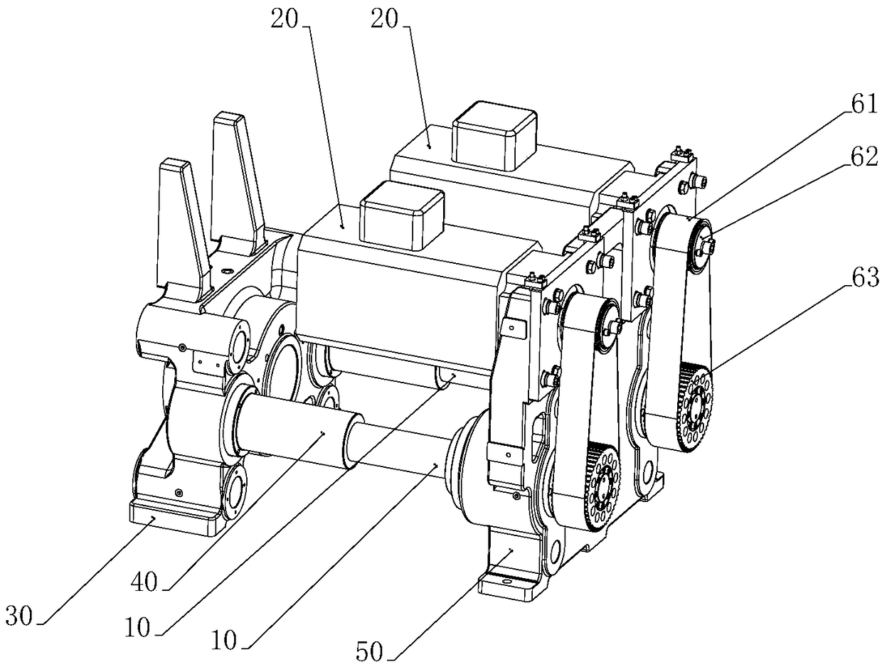
[0004] The invention provides a glue injection driving mechanism to solve the problem of complex structure of the glue injection driving mechanism in the prior art

Method used


Image

  • Glue jet drive mechanism
  • Glue jet drive mechanism

Examples


Embodiment Construction

[0021] The technical solutions in the embodiments of the present invention will be clearly and completely described below in conjunction with the accompanying drawings in the embodiments of the present invention. Obviously, the described embodiments are only a part of the embodiments of the present invention, rather than all the embodiments. The following description of at least one exemplary embodiment is actually only illustrative, and in no way serves as any limitation to the present invention and its application or use. Based on the embodiments of the present invention, all other embodiments obtained by those of ordinary skill in the art without creative work shall fall within the protection scope of the present invention.

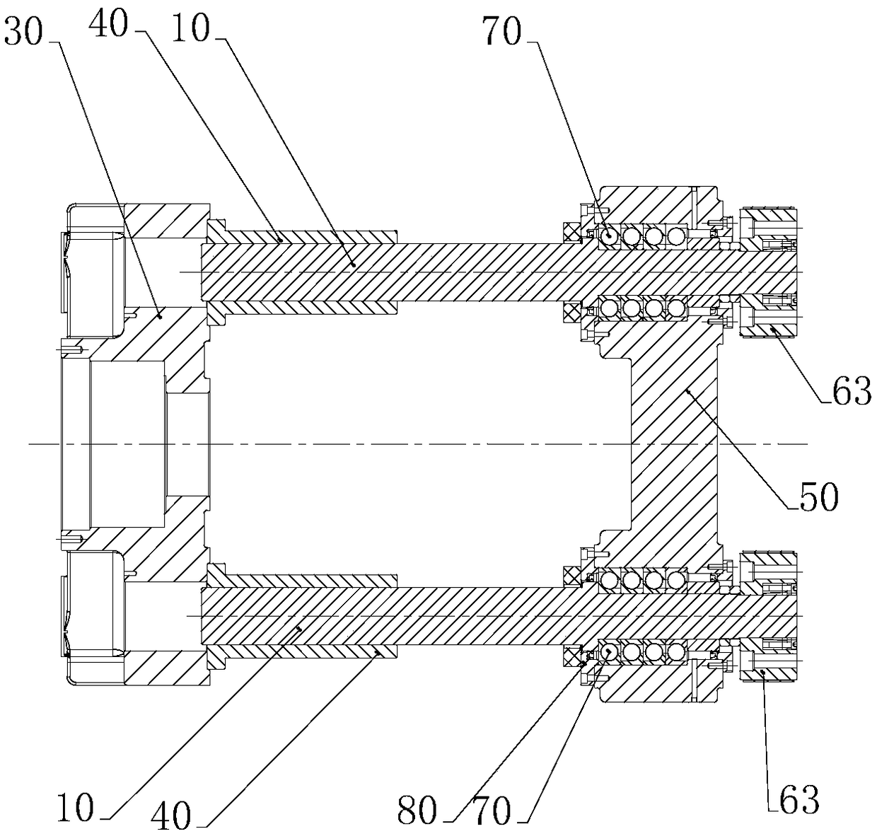
[0022] Such as figure 1 with figure 2 As shown, the embodiment of the present invention provides a glue injection driving mechanism, which includes a plurality of screw rods 10, a plurality of motors 20 and a controller. Wherein, a plurality of motors 2...


PUM


Abstract

The invention provides a glue jet drive mechanism. The glue jet drive mechanism comprises a plurality of screw rods, a plurality of motors and a controller, wherein the multiple motors correspond to the multiple screw rods one by one and are connected with the corresponding screw rods so as to drive the corresponding screw rods to rotate; and the controller is connected with the multiple motors soas to control the multiple motors to move synchronously. By means of the technical scheme, the technical problem that a glue jet drive mechanism is complicated in structure in the prior art can be solved.

Description

Technical field [0001] The invention relates to the technical field of injection molding machines, in particular to a glue injection driving mechanism. Background technique [0002] At present, in the all-electric injection molding machine industry, due to the insufficient load capacity of a single motor and a single screw, it cannot meet application requirements. By changing the single-motor single-screw drive mechanism to the dual-motor double-screw drive mechanism, the load-bearing capacity of the drive mechanism can be doubled to meet the load demand of the injection screw of 50mm or more. [0003] In the prior art, a dual-motor dual-screw drive mechanism is driven by two motors to drive a transition wheel, and the dual-screws are synchronously driven to move synchronously through the transition wheel. The structure of this driving mechanism in the prior art is relatively complicated and occupies a large space. Summary of the invention [0004] The invention provides a glue in...

Claims


Application Information

Patent Timeline
Patent Type & Authority Applications(China)
IPC IPC(8): B29C45/46B29C45/17
CPCB29C45/46B29C2045/1792
Inventor 钱双林杨桃甲莫玉麟张天翼张秀峰马徐武
Owner ZHUHAI GREE INTELLIGENT EQUIP CO LTD
Learn More