Ink jet printing method

An inkjet printing and print-driven technology, applied in the field of inkjet printing, can solve problems such as inability to print images of qualified quality, and achieve the effects of improving printing efficiency, ensuring printing quality, and avoiding paper waste.

Active Publication Date: 2018-12-28
BEIJING MEIKEYI
8 Cites 1 Cited by

AI-Extracted Technical Summary

Problems solved by technology

Then in this abnormal state, it is impossible to print an image of acceptable quality...

Method used

In actual printing process, the 1st section uses E pulse as driving pulse, and the image quality of printing is good, through trial and error, after firing frequency reaches 10kHz, promptly switches to F pulse and drives during the 2nd section, can Compensate for the instability of the ink dr...

Abstract

The invention discloses an ink jet printing method. The ink jet printing method is characterized in that the ink jet printing method comprises the following steps that a, an ejection characteristic curve of a spray nozzle is subjected to interval partition according to waveform change and printing effects; b, the partitioned sections are tested to find printing driving pulses corresponding to sections separately; and c, printing is officially started, and in the printing process, a mode of switching the corresponding printing driving pulses is adopted in a spray nozzle control board to performdrive control on the sections. The printing method can switch compensation driving voltage or increase/decrease image printing resolution ratio under the condition that the ejection state is abnormalwhen a piezoelectric ceramic in the spray nozzle resonates during the increase of the ignition frequency, so that good printing quality is ensured; qualified printed images can be always printed in the process of accelerating the printing medium to a high transmission speed, so that the printing efficiency is improved.

Application Domain

Technology Topic

Image

  • Ink jet printing method
  • Ink jet printing method
  • Ink jet printing method

Examples

  • Experimental program(3)

Example Embodiment

[0029] Example one
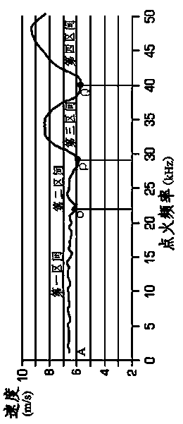
[0030] figure 1 It is a schematic diagram of the relationship between the ignition frequency of a nozzle and the ejection speed of ink droplets. Specifically, the ignition frequency of the nozzle is within the range of 0 to 50kHz (50kHz is the maximum ignition frequency of the nozzle). Most ink droplets (above 90%) The velocity injection curve of the nozzle. It can be seen from the figure that the ignition frequency reaches 6.5m/s from the A position, and then basically stabilizes, the speed changes insignificantly, until the O point, the corresponding nozzle ignition frequency at the O point is 22kHz. This ignition frequency interval is defined as the first interval. The ignition frequency of the first interval is greater than 0kHz and less than 22kHz; after O point, the waveform indicating the speed change begins to have a small amount of fluctuations, and the corresponding nozzle ignition frequency at point P is 29kHz, the ignition frequency interval from point O to point P is defined as the second interval. The ignition frequency of the second interval is greater than 22kHz and less than 29kHz; after point P, the speed changes more obviously, and the corresponding nozzle at the position of Q point The ignition frequency is 40kHz. The ignition frequency interval from point P to point Q is defined as the third interval. The ignition frequency of the third interval is greater than 29kHz and less than 40kHz; the speed fluctuation after Q point is more severe, and the interval after Q point Defined as the fourth interval, the ignition frequency of the fourth interval is greater than 40kHz and less than 50kHz. After the printer is started, as the printing medium accelerates, the nozzle ignition frequency gradually increases. When the ignition frequency is within the first interval, the ink droplet ejection speed is basically stable, and the image quality printed by the nozzle is easy to control Within the qualified effect, when the firing frequency of the nozzle increases to the second interval, the ejection speed of ink droplets fluctuates, and the quality of the image printed by the nozzle is slightly affected, which is not obvious after careful identification. When the nozzle ignition frequency passes through point P, and the ignition frequency exceeds 29kHz in the third and fourth intervals, the ejection velocity of ink drops will fluctuate more and more, and the image that continues to accelerate the ejection may appear white lines, jumps, and Satellite points or lines are not straight and other effects, resulting in a significant drop in the quality of the ejected graphics.
[0031] As the speed fluctuations in the third and fourth sections are getting bigger and bigger, usually during the printing process, the speed will not continue to increase after accelerating to 29kHz, and then the uniform speed one-pass inkjet printing is performed at a constant firing frequency of 29kHz. If printing images with 600dpi resolution, the printing speed V of the printer when the ignition frequency is 29kHz 29kHz =29000Hz/600dpi×2.54=122.8cm/s. However, the higher the ignition frequency, the faster the printing speed, and the higher the work efficiency. For example, if the ignition frequency is 40kHz, the printer's printing speed V 40kHz =40000Hz/600dpi×2.54≈169cm/s, when the nozzle can reach the maximum ignition frequency of 50kHz, the printer can reach the theoretical maximum printing speed V 50kHz =50000Hz/600dpi×2.54≈212cm/s.
[0032] figure 2 It is a schematic diagram of the voltage applied under normal operation of the print head. In the figure, the rise time Tr of the waveform is 2.0us, the fall time Tf is 2.0us, the pulse duration Tw is 4.5us, and the voltage range is 17-19V. When the nozzle ignition frequency is in the first interval and the second interval, use such figure 2 The driving pulse shown can realize the high-quality image produced by the nozzle. However, if the driving pulse continues to be used, as the transmission speed of the printing medium increases, the ignition frequency becomes larger and larger. When the ignition frequency reaches the third interval and the fourth interval, a quality problem that can be recognized by the naked eye will appear, and the printing speed When the bottleneck is reached, it cannot continue to improve. Through trial and error, find the compensation pulse-B pulse and C pulse. When the ignition frequency exceeds 29kHz and is less than 40kHz, that is, when the ignition frequency is in the third interval, the FPGA (or software) of the circuit control board/printer control board controls the application of B pulse to the nozzle, such as image 3 As shown, after using the B pulse, the unstable fluctuation of the ink droplet ejection velocity in the third interval in the characteristic curve of the nozzle can be compensated, and an image that can be used when the quality reaches the standard can be printed. When the ignition frequency exceeds 40kHz and is less than 50kHz, that is, when the ignition frequency is in the fourth interval, the FPGA (or software) of the circuit control board/printer control board controls the application of C pulse to the nozzle, such as Figure 4 As shown, after using the C pulse, the unstable fluctuation of the ink droplet ejection speed in the fourth interval in the characteristic curve of the nozzle can be compensated, and the image that can be used when the quality reaches the standard can be printed.
[0033] It should be pointed out that because different inks will also affect the printing effect, the compensation waveform of the present invention can also use pulses of other shapes, mainly for the rise time Tr, fall time Tf, pulse duration Tw and voltage range of the waveform. It is not limited to the waveform curve drawn in the figure. What the present invention wants to protect is a method for voltage pulse compensation in an unstable region for the ignition characteristics of the nozzle.
[0034] In addition, according to this principle, when the ignition frequency is in the second range, that is, when the ignition frequency is greater than 22kHz and less than 29kHz, although the quality of the image can be printed out, the quality will be slightly different if you look carefully, such as multiple satellite points, etc. At this time, you can also choose Figure 5 Driven by the A'pulse as shown, the inkjet effect can be improved and more impeccable.

Example Embodiment

[0035] Example two
[0036] For the above figure 1 When using the nozzle with the characteristics of the nozzle shown in the figure, it is also possible to reduce the image printing resolution to avoid the problem of poor print quality in the third and fourth sections. Specifically, if the original resolution of the printed image is 600dpi, the image effect printed by the nozzle at the beginning of the acceleration phase meets the requirements. After the ignition frequency reaches 29kHz, that is, the P point, the print quality has problems, then the printer will print at 29kHz. Speed ​​V 29kHz =29000Hz/600dpi×2.54=122.8cm/s. After 29kHz or P dot, start to use 400dpi resolution for inkjet printing, you can print out images that meet the requirements. Similarly, at the position of Q point when the ignition frequency is 40kHz, the printer's printing speed V 40kHz =40000Hz/600dpi×2.54≈169cm/s, if 400dpi is used for printing in the third interval, the actual ignition frequency required for the image at point Q is 169cm/s÷2.54×400dpi≈26.6kHz, which is the actual ignition required The frequency is in the second interval where the waveform is relatively stable and qualified images can be printed. For another example, when the nozzle is at an ignition frequency of 43kHz (in the fourth interval), the printing speed when printing 600dpi resolution images is 43000Hz/600dpi×2.54=182.0cm/s, but the actual ignition frequency used after reducing the resolution to 400dpi It is 182.0cm/s÷2.54×400dpi=28.7kHz. The ignition frequency is in the second interval where the waveform is relatively stable and qualified images can be printed. Therefore, this method of reducing the resolution can bypass the third, which is more volatile. Interval and the fourth interval, so as to print out images of acceptable quality.
[0037] It should be noted that after the printing resolution is reduced, the printed image may be slightly lighter in color, but it can still meet the needs of the user. The specific reduction of the resolution is determined according to the actual situation. This embodiment is only for illustration This principle does not limit the specific number.

Example Embodiment

[0038] Example three
[0039] Such as Image 6 Shown is the nozzle characteristic curve of another nozzle during printing. It can be seen from the curve that the ink droplet ejection speed tends to be stable when the ignition frequency of this nozzle is less than 10kHz. This interval is defined as the first interval; ignition When the frequency is in the range of 10kHz to 16kHz, the ink droplet ejection speed fluctuates significantly. This interval is defined as the second interval; after the ignition frequency is greater than 16kHz, the ink droplet ejection speed becomes stable again until the maximum ignition frequency of the nozzle is 20kHz , Define this interval as the third interval.
[0040] In the process of accelerating the transmission of the printing medium, the ignition frequency gradually increases. In the first interval, since the ejection speed of ink drops is basically stable, the printed image effect can also be guaranteed. If the image resolution printed by the nozzle is 600dpi, the printer's printing speed V when the ignition frequency is 10kHz at the end of the first interval 10kHz =10000Hz/600dpi×2.54≈42.3cm/s; in the second interval, due to the obvious changes in the ejection speed of ink droplets, the printed image effect is also relatively poor, and white lines, jumps, satellite points or For images with poor quality such as uneven lines, the printer’s printing speed V when the ignition frequency is 16kHz at the end of the second interval 16kHz =16000Hz/600dpi×2.54≈67.7cm/s; in the third interval, because the ejection speed of the ink drops returns to stability, the printed image effect is better again. In theory, the nozzle can reach the maximum ignition frequency of 20kHz When the printer can reach the maximum printing speed V 20kHz =20000Hz/600dpi×2.54≈84.6cm/s.
[0041] If the problem of poor jet image quality in the second section cannot be resolved, the printing speed cannot be higher than the maximum ignition frequency in the first section, which is 10kHz; or even if the ignition frequency continues to increase to the third section, stable printing is achieved. However, it is unavoidable that an image that does not meet the quality requirements is printed when passing through the second interval, and this section of the printing medium will be wasted, resulting in an increase in subsequent costs.
[0042] In the actual printing process, the E pulse is used as the driving pulse in the first interval, and the printed image quality is good. After repeated tests, after the ignition frequency reaches 10kHz, that is, the second interval is switched to F pulse for driving, which can compensate for this If the ejection speed of the ink droplets is unstable within the ignition frequency, a good image can be printed. After the ignition frequency reaches 16kHz, the ignition frequency enters the third interval, and the driving pulse is switched again to use E pulse, so that the entire process can be printed. To produce high-quality images.
[0043] If the E pulse is used throughout the entire process instead of switching the pulse, the resolution can also be changed to compensate, including increasing or decreasing the resolution. For example, the original printing resolution is 600dpi, and the printing speed V of the printer when the ignition frequency of the M point at the end of the first interval is 10kHz 10kHz =10000Hz/600dpi×2.54≈42.3cm/s. At this time, the switching printing resolution is reduced to 480dpi, then the actual ignition frequency required when printing at point M is 42.3cm/s÷2.54×480dpi≈7.99kHz, this ignition The frequency is converted to the first interval where the waveform is relatively stable and can print out the image with quality. Printing speed V for printing 600dpi images at N points at the end of section 2 16kHz =16000Hz/600dpi×2.54≈67.7cm/s, then the actual ignition frequency required when printing at point N after switching to 720dpi is 67.7cm/s÷2.54×480dpi≈19.2kHz, the ignition frequency will be converted to a larger waveform Stable to be able to print out in the third section of the quality image. The printed image has a slight lightening or darkening phenomenon, which does not affect the visual effect of the image. If the barcode is printed, it will not affect the scanning and recognition of the barcode.

PUM

no PUM

Description & Claims & Application Information

We can also present the details of the Description, Claims and Application information to help users get a comprehensive understanding of the technical details of the patent, such as background art, summary of invention, brief description of drawings, description of embodiments, and other original content. On the other hand, users can also determine the specific scope of protection of the technology through the list of claims; as well as understand the changes in the life cycle of the technology with the presentation of the patent timeline. Login to view more.

Similar technology patents

Novel 3D printer

Owner:广州瑞通增材科技有限公司

Printing method and device

Owner:BEIJING DREAM INK TECH CO LTD

Gravure plate roller and sleeve carving process thereof

PendingCN110978745ASufficient inkGuaranteed print qualityRotary pressesForme preparationComposite materialEngineering
Owner:青岛黎马敦包装有限公司 +1

Classification and recommendation of technical efficacy words

  • Guaranteed print quality
  • Improve printing efficiency

Cyclic ink supply method and cyclic ink supply system

InactiveCN101391530AGuaranteed print qualityReduce system complexityPrintingNozzlePulp and paper industry
Owner:PEKING UNIV FOUNDER GRP CO LTD +2

Two-dimension code printing quality online assessment method

ActiveCN105160339AGuaranteed print qualityAvoid wasting time and moneyCharacter and pattern recognitionSample imageQuality characteristics
Owner:SICHUAN UNIV

Ink-jet printing device

ActiveCN105479949AGuaranteed print qualityReduce printing costTypewritersPrinting inkInkjet printing
Owner:BEIJING MEIKEYI

3D printing method based on force feedback system

Owner:GUANGZHOU HEYGEARS INTELLIGENT TECH CO LTD

Multifunctional ink box

InactiveCN108859418AUniform ink densityGuaranteed print qualityOther printing apparatusEngineeringMultiple function
Owner:仁怀市云侠网络科技有限公司

3D printing method and 3D printer

InactiveCN103231513AReduce printing timeImprove printing efficiencyThermal printingEngineering
Owner:温州启龙电子科技有限公司
Why Eureka
Try Eureka