
Hybrid power systems and hybrid vehicles

A hybrid power system and engine technology, applied in hybrid vehicles, motor vehicles, power plants, etc., can solve the problems of engine ICE working point limitation, engine ICE motor EM cannot be realized at the same time, and achieve the effect of avoiding working point limitation

Inactive Publication Date: 2018-12-28
SCHAEFFLER TECH AG & CO KG
View PDF0 Cites 6 Cited by
  • Summary
  • Abstract
  • Description
  • Claims
  • Application Information

AI Technical Summary

Problems solved by technology

At this time, when both the engine ICE and the motor EM are used for driving, the speed of the engine ICE is the same as the speed of the motor EM, resulting in the limitation of the operating point of the engine ICE
[0007] In addition, in the above hybrid system, the operating point with the highest efficiency of the engine ICE and the highest efficiency operating point of the motor EM cannot be simultaneously realized.

Method used


Image

  • Hybrid power systems and hybrid vehicles
  • Hybrid power systems and hybrid vehicles
  • Hybrid power systems and hybrid vehicles

Examples


Embodiment Construction

[0036] The specific implementation manners of the present invention will be described in detail below in conjunction with the accompanying drawings. It should be noted that, in the present invention, "transmission coupling" means that the driving force / torque can be directly transmitted between two components or the driving force / torque can be transmitted through a necessary gear transmission mechanism or clutch.

[0037] (Structure of a hybrid system)

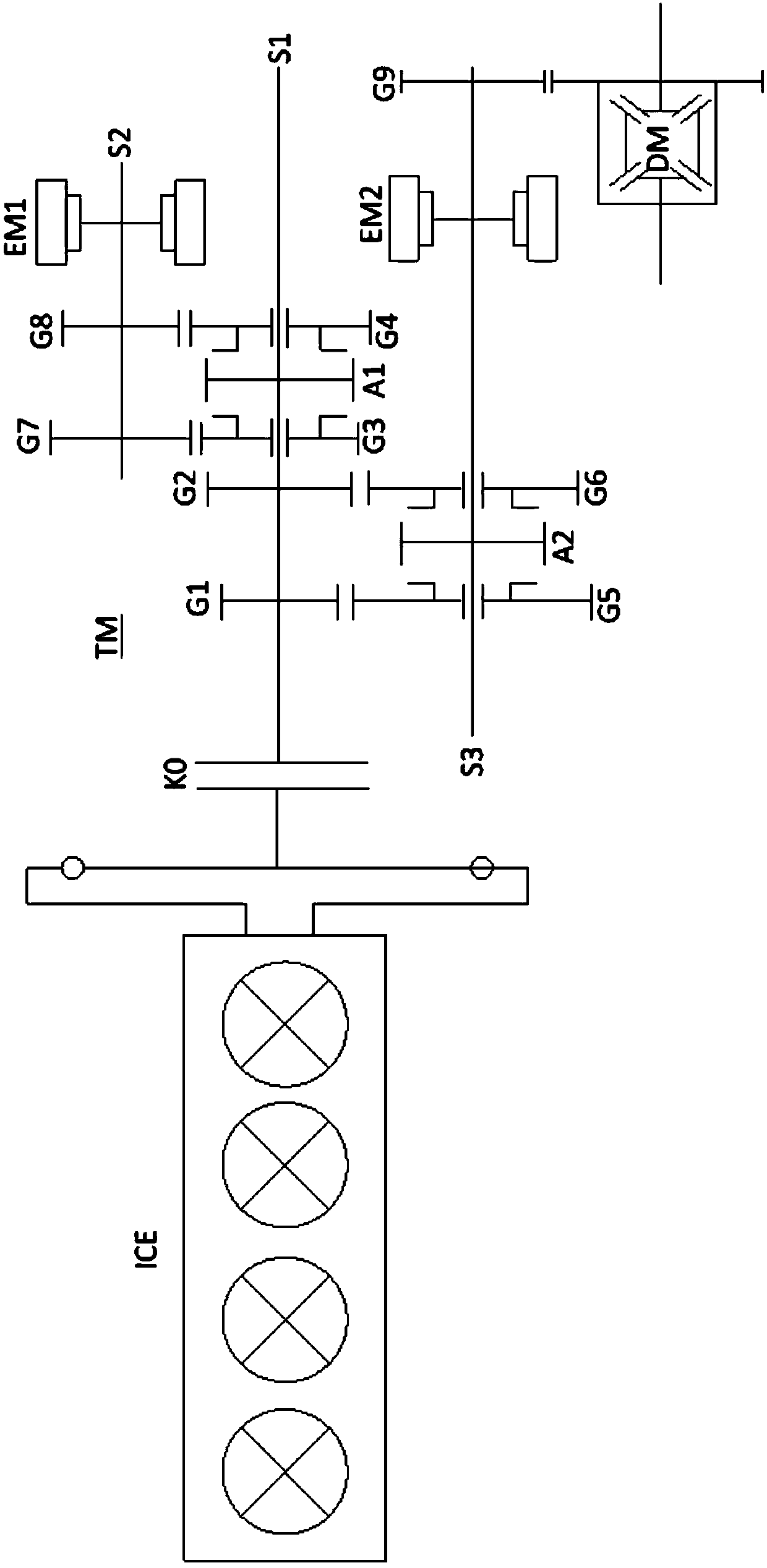
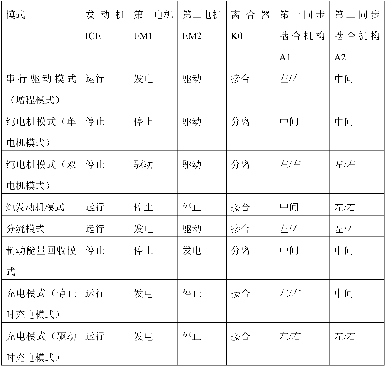
[0038] Such as figure 2As shown, the hybrid system according to an embodiment of the present invention includes an engine ICE, a first electric machine EM1 , a second electric machine EM2 , a clutch K0 , a transmission TM and a differential DM.

[0039] In the present embodiment, the engine ICE is a four-cylinder engine. However, the engine ICE is not limited to a four-cylinder engine, and may be other types of engines. Such as figure 2 As shown, the engine ICE is located on the opposite side to the side of the transmiss...


PUM


Abstract

FIELD OF THE INVENTION that present invention relate to the field of hybrid vehicles, and more particularly to hybrid powertrain and hybrid vehicles. The hybrid system includes a transmission including a first input shaft, a second input shaft, an output shaft, a plurality of synchronous engagement mechanisms and a plurality of gear gears disposed on each shaft, each shaft being selectively drivably coupled through the plurality of synchronous engagement mechanisms and the plurality of gear gears; An engine and a clutch, the engine being drivingly coupled to the first input shaft via the clutch; A first motor having an input / output shaft drivingly coupled to a second input shaft; And a second motor whose input / output shaft is drivingly coupled to the output shaft. Thus, when the engine andthe electric motor are used for driving, the speed of the engine and the speed of the electric motor do not have to be the same, so that the problem that the operating point of the engine is limitedcan be avoided; In addition, the most efficient operating point of the engine and the most efficient operating point of the motor can be realized simultaneously.

Description

technical field [0001] The present invention relates to the field of hybrid vehicles, and more particularly, the present invention relates to a hybrid system and a hybrid vehicle including the hybrid system. Background technique [0002] Such as figure 1 As shown, there is a hybrid system including an engine ICE, a clutch K0, an electric motor EM and a transmission TM. [0003] Specifically, the engine ICE is a four-cylinder engine. The engine ICE is located on the opposite side of the transmission TM with respect to the electric motor EM, and the output shaft of the engine ICE is drive-coupled to the input shaft of the transmission TM via the clutch K0. When the clutch K0 is engaged, the output shaft of the engine ICE is coupled with the input shaft of the transmission TM; when the clutch K0 is disengaged, the transmission coupling between the output shaft of the engine ICE and the input shaft of the transmission TM is disconnected. [0004] Clutch K0 is a conventional c...

Claims


Application Information

Patent Timeline
Patent Type & Authority Applications(China)
IPC IPC(8): B60K6/26B60K6/42B60K6/46B60K6/547B60K6/387
CPCB60K6/26B60K6/387B60K6/42B60K6/46B60K6/547Y02T10/62
Inventor 陈鑫
Owner SCHAEFFLER TECH AG & CO KG
Learn More