Heat exchange tube and air conditioner

A technology of heat exchange tubes and tube bodies, which is applied in the direction of heat sinks, tubular components, heat exchange equipment, etc., and can solve problems such as flooding on the surface of liquid refrigerants

Inactive Publication Date: 2018-12-28
GREE ELECTRIC APPLIANCES INC
View PDF5 Cites 2 Cited by
  • Summary
  • Abstract
  • Description
  • Claims
  • Application Information

AI Technical Summary

Problems solved by technology

[0005] The embodiment of the present invention provides a heat exchange tube and an air conditioner to solve the tech

Method used


Image

  • Heat exchange tube and air conditioner
  • Heat exchange tube and air conditioner
  • Heat exchange tube and air conditioner

Examples


Embodiment Construction

[0030] In order to make the object, technical solution and advantages of the present invention clearer, the present invention will be described in further detail below in conjunction with the embodiments and accompanying drawings. Here, the exemplary embodiments and descriptions of the present invention are used to explain the present invention, but not to limit the present invention.

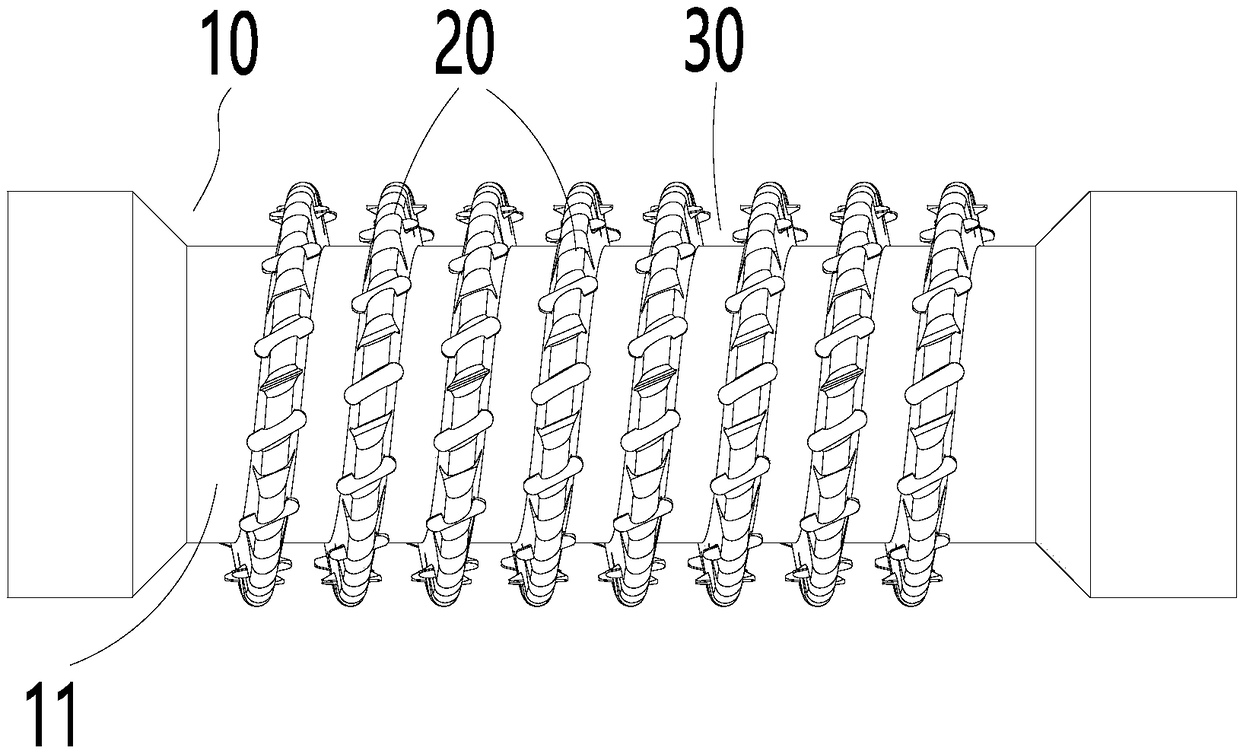
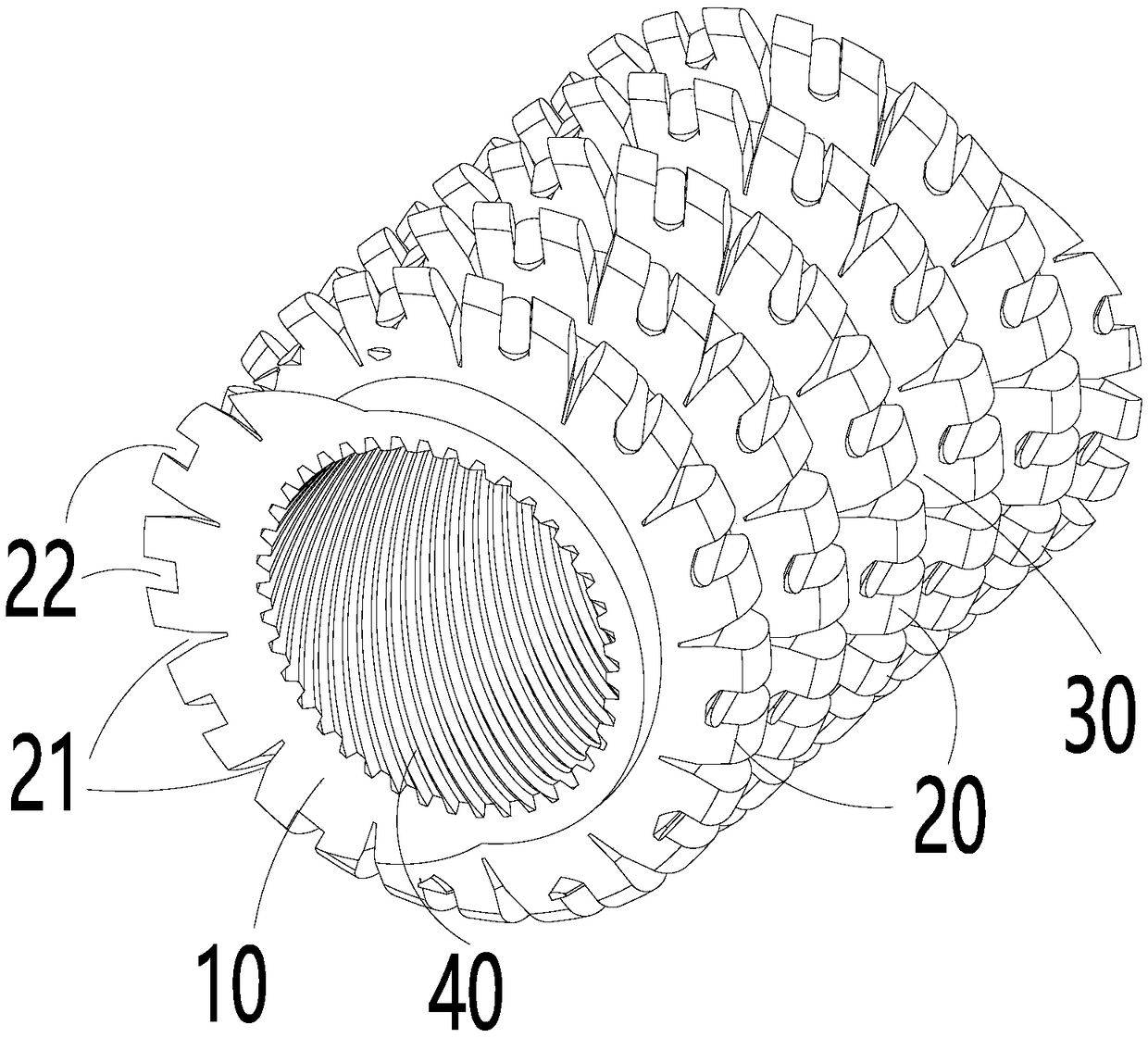
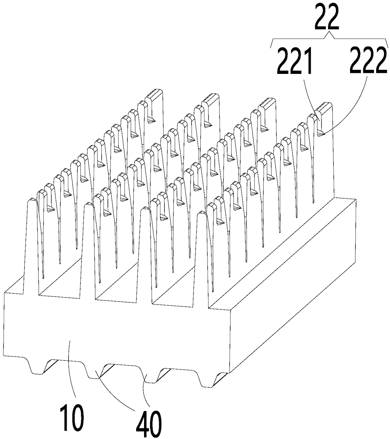
[0031] figure 1 An embodiment of the heat exchange tube of the present invention is shown, the heat exchange tube includes a tube body 10 and fins 20 arranged on the outer surface 11 of the tube body 10 , channels 30 are formed between adjacent fins 20 . The fins 20 are provided with communication grooves 21 , the communication grooves 21 communicate with the adjacent channels 30 , and the communication grooves 21 are used for circulating refrigerant.

[0032] Applying the technical scheme of the present invention, through the communication groove 21 opened on the fin 20, the adjacent channels...


PUM


Abstract

The invention provides a heat exchange tube and an air conditioner. The heat exchange tube comprises a tube body and fins arranged on the outer surface of the tube body. Channels are formed between the adjacent fins. Communication grooves are formed in the fins to enable the adjacent channels to communicate, and the communication grooves are used for circulating refrigerants. By utilizing the technical scheme, the adjacent channels can communicate through the communication grooves formed in the fins, the area of discharging channels for condensed liquid refrigerants is increased, the refrigerant discharging capacity is enhanced, and the refrigerants can better circulate on the surface of the heat exchange tube. Therefore, the situation that the thickness of the liquid refrigerants on the surface of the heat exchange tube is increased too much, and consequently heat resistance is increased and heat exchange efficiency is lowered can be avoided.

Description

technical field [0001] The invention relates to the technical field of refrigeration, in particular to a heat exchange tube and an air conditioner. Background technique [0002] In the air conditioning and refrigeration industry, water-cooled condensers have developed rapidly due to their compact structure and wide applicability. High efficiency, energy saving and replacement of new refrigerants are still the main research directions at present. Most of the water-cooled heat exchangers are horizontal shell-and-tube heat exchangers, with freon in the shell and water in the tube. In the condenser, a factor that has a relatively large impact on its heat transfer is the performance of the heat transfer tubes in the shell. Inside the shell side, the refrigerant on the outside of the condenser tube undergoes a phase change to perform heat exchange. The refrigerant condenses outside the tube to form a liquid film covering the surface of the heat exchange tube. The existence of th...

Claims


Application Information

Patent Timeline
IPC IPC(8): F28F1/42F25B39/04
CPCF25B39/04F25B2339/047F28F1/42F28F2215/10
Inventor 刘华张治平岳清学胡东兵王春连胡海利
Owner GREE ELECTRIC APPLIANCES INC
Why Eureka
Try Eureka