A method and apparatus for signal transmission
A technology of signal transmission and transmission method, which is applied in the field of communication and can solve problems such as waste
- Summary
- Abstract
- Description
- Claims
- Application Information
AI Technical Summary
Problems solved by technology
Method used
Image
Examples
Embodiment 1
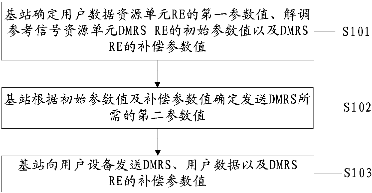
[0189] An embodiment of the present invention provides a signal sending method, such as figure 1 As shown, the method includes:
[0190] S101. The base station determines a first parameter value of a user data resource element RE, an initial parameter value of a demodulation reference signal resource element DMRS RE, and a compensation parameter value of a DMRS RE.
[0191] Wherein, the user data RE is used to carry user data, the first parameter value is used to instruct the base station to send user data with the first parameter value, and the DMRS RE is used to carry a demodulation reference signal DMRS.
[0192] Optionally, the initial parameter value may be the initial power value or the initial amplitude value; the compensation parameter value may be the power compensation value or the amplitude compensation value; the first parameter value may be the first power value or The first amplitude value.
[0193] In a MIMO system, the array gain brought by multiple antennas ...
Embodiment 2
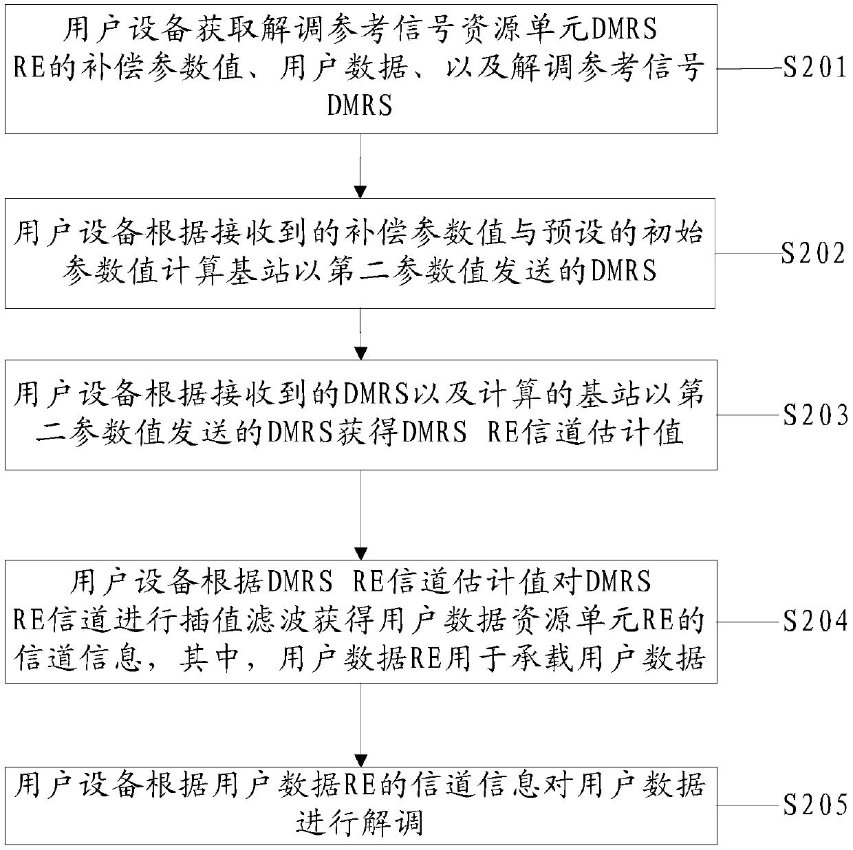
[0224] An embodiment of the present invention provides a signal sending method, such as figure 2 As shown, the method includes:
[0225] S201. The user equipment acquires a compensation parameter value of a demodulation reference signal resource element DMRS RE, user data, and a demodulation reference signal DMRS.
[0226] Wherein, the DMRS RE is used to bear the demodulation reference signal DMRS.
[0227] Optionally, the compensation parameter value may be a power compensation value or an amplitude compensation value.
[0228] High-dimensional antenna configuration system, the high-dimensional antennas at the transmitting and receiving ends bring considerable array gain to user data demodulation, and the SINR at the user data operating point can be very low. However, because the array gain of the high-dimensional antenna cannot be obtained, DMRS can only Work in areas with high signal-to-interference-noise ratio, otherwise effective channel estimation cannot be achieved. ...
Embodiment 3
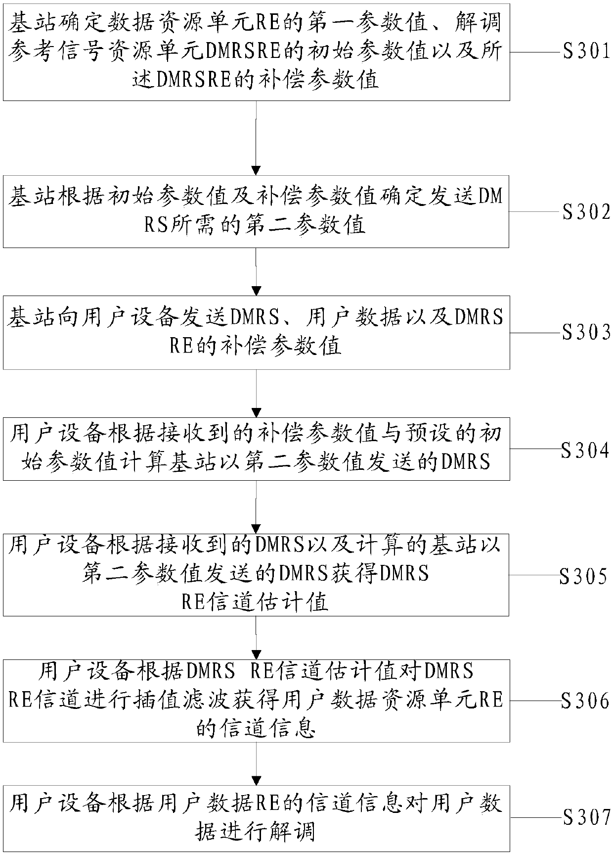
[0243] An embodiment of the present invention provides a signal sending method, such as image 3 As shown, the method includes:
[0244] S301. The base station determines a first parameter value of a user data resource element RE, an initial parameter value of a demodulation reference signal resource element DMRS RE, and a compensation parameter value of a DMRS RE.
[0245] Wherein, the user data RE is used to carry user data, the first parameter value is used to instruct the base station to send user data with the first parameter value, and the DMRS RE is used to carry a demodulation reference signal DMRS.
[0246] Optionally, the initial parameter value can be an initial value of power or an initial value of amplitude;
[0247] The compensation parameter value may be a power compensation value or an amplitude compensation value; the first parameter value may be a first power value or a first amplitude value.
[0248] High-dimensional antenna configuration system, the high-...
PUM
 Abstract
Description
Claims
Application Information
 - R&D
- Intellectual Property
- Life Sciences
- Materials
- Tech Scout
- Unparalleled Data Quality
- Higher Quality Content
- 60% Fewer Hallucinations
Browse by: Latest US Patents, China's latest patents, Technical Efficacy Thesaurus, Application Domain, Technology Topic, Popular Technical Reports.
© 2025 PatSnap. All rights reserved.Legal|Privacy policy|Modern Slavery Act Transparency Statement|Sitemap|About US| Contact US: help@patsnap.com


