Signal transmission method and device

A technology of signal transmission and transmission method, which is applied in the field of communication and can solve problems such as waste

Active Publication Date: 2015-07-01
HUAWEI TECH CO LTD
View PDF6 Cites 24 Cited by
  • Summary
  • Abstract
  • Description
  • Claims
  • Application Information

AI Technical Summary

Problems solved by technology

[0007] Embodiments of the present invention provide a signal transmission method and device, which can ensure the correctness of channel estimat

Method used


Image

  • Signal transmission method and device
  • Signal transmission method and device
  • Signal transmission method and device

Examples


Embodiment 1

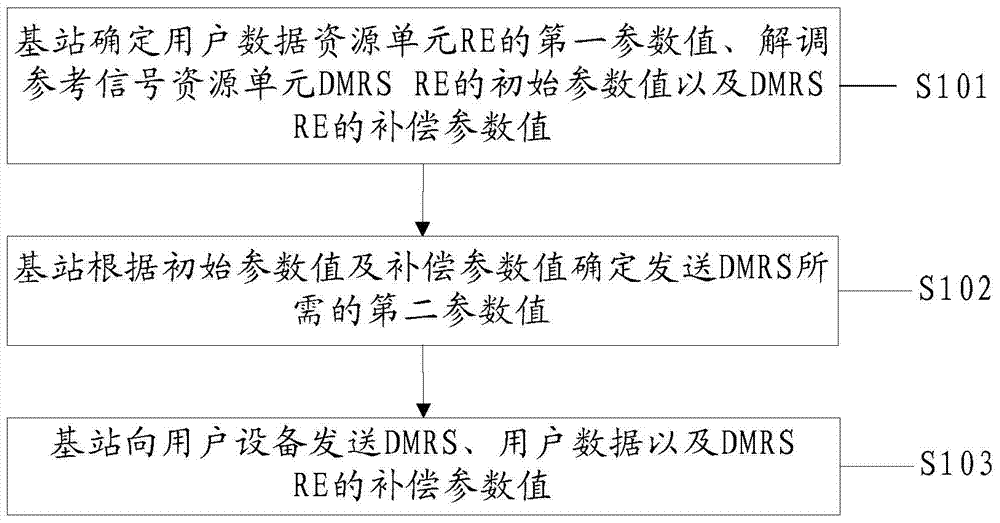
[0189] An embodiment of the present invention provides a signal sending method, such as figure 1 As shown, the method includes:

[0190] S101. The base station determines a first parameter value of a user data resource element RE, an initial parameter value of a demodulation reference signal resource element DMRS RE, and a compensation parameter value of the DMRS RE.

[0191] Wherein, the user data RE is used to carry user data, the first parameter value is used to instruct the base station to send user data with the first parameter value, and the DMRS RE is used to carry a demodulation reference signal DMRS.

[0192] Optionally, the initial parameter value may be the initial power value or the initial amplitude value; the compensation parameter value may be the power compensation value or the amplitude compensation value; the first parameter value may be the first power value or The first amplitude value.

[0193] In a MIMO system, the array gain brought by multiple antenna...

Embodiment 2

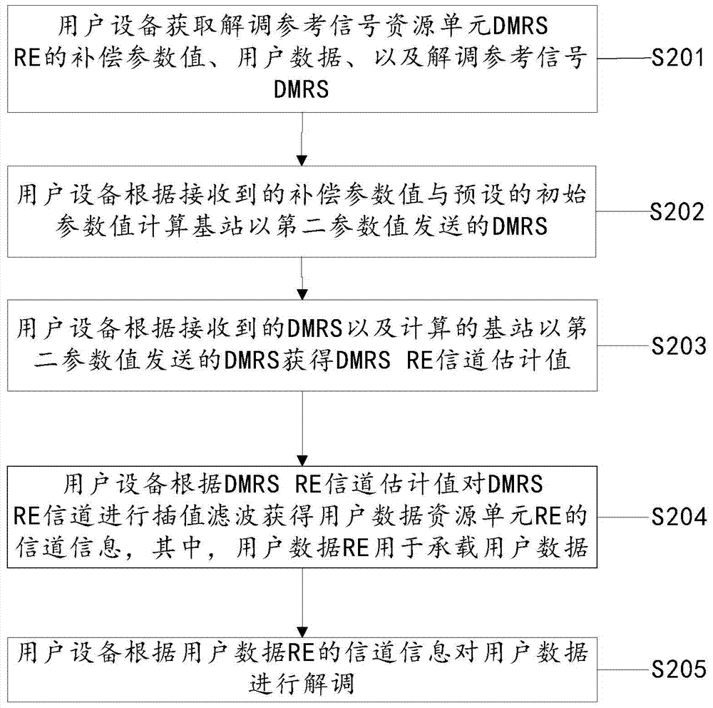
[0224] An embodiment of the present invention provides a signal sending method, such as figure 2 As shown, the method includes:

[0225] S201. The user equipment acquires a compensation parameter value of a demodulation reference signal resource element DMRS RE, user data, and a demodulation reference signal DMRS.

[0226] Wherein, the DMRS RE is used to bear the demodulation reference signal DMRS.

[0227] Optionally, the compensation parameter value may be a power compensation value or an amplitude compensation value.

[0228] High-dimensional antenna configuration system, the high-dimensional antennas at the transmitting and receiving ends bring considerable array gain to user data demodulation, and the SINR at the user data operating point can be very low. However, because the array gain of the high-dimensional antenna cannot be obtained, DMRS can only Work in areas with high signal-to-interference-noise ratio, otherwise effective channel estimation cannot be achieved. ...

Embodiment 3

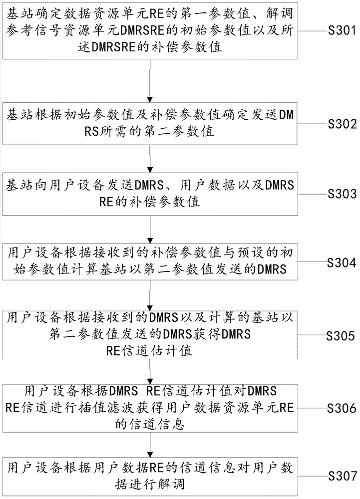
[0243] An embodiment of the present invention provides a signal sending method, such as image 3 As shown, the method includes:

[0244] S301. The base station determines a first parameter value of a user data resource element RE, an initial parameter value of a demodulation reference signal resource element DMRS RE, and a compensation parameter value of a DMRS RE.

[0245] Wherein, the user data RE is used to carry user data, the first parameter value is used to instruct the base station to send user data with the first parameter value, and the DMRS RE is used to carry a demodulation reference signal DMRS.

[0246] Optionally, the initial parameter value can be an initial value of power or an initial value of amplitude;

[0247] The compensation parameter value may be a power compensation value or an amplitude compensation value; the first parameter value may be a first power value or a first amplitude value.

[0248] High-dimensional antenna configuration system, the high-...


PUM


Abstract

The present invention relates to the field of communications. Embodiments of the present invention provide a signal sending method and device, which can effectively solve the problem of resource waste of user data resource elements and improve system power utilization. The method comprises: a base station determining a first parameter value of a user data Resource Element (RE), an initial parameter value of a Demodulation Reference Signal Resource Element (DMRS RE) and a compensation parameter value of the DMRS RE; the base station determining a second parameter value required for sending a DMRS according to the initial parameter value and the compensation parameter value; and the base station sending the DMRS, user data and the compensation parameter value to a user equipment, so that the user equipment demodulates the user data.

Description

technical field [0001] The present invention relates to the communication field, in particular to a signal sending method and device. Background technique [0002] With the rapid development of communication technology, high speed, large capacity and wide coverage have become the main features of modern communication systems, to solve other problems such as serious fading and intersymbol interference caused by the continuous expansion of communication range and more complex and diverse communication environments. The problem of non-ideal characteristics is particularly important. [0003] Multiple-input multiple-output (MIMO, Multi-input Multi-output) technology utilizes resources in the spatial dimension to enable signals to obtain array gain, multiplexing gain, diversity gain, and interference cancellation gain in space without increasing the system bandwidth. Double the capacity and spectrum efficiency of the communication system. [0004] With the continuous improvemen...

Claims


Application Information

Patent Timeline
IPC IPC(8): H04L1/06H04L25/02
CPCH04L1/06H04L5/0051H04W52/325H04W52/0203Y02D30/70H04W72/23H04W52/04H04W72/0473H04W88/02H04W88/08
Inventor 陈大庚刘永王艺
Owner HUAWEI TECH CO LTD
Why Eureka
Try Eureka