Stirring device of storage battery separation plate slurry tank

A battery separator and stirring device technology, which is used in mixer accessories, transportation and packaging, dissolving, etc., can solve the problems of insufficient mixing of liquids, unidirectional rotation of stirring blades, low stirring efficiency, etc. Large stirring force, sufficient stirring effect

Inactive Publication Date: 2019-01-01
枣庄市东昌玻纤实业有限公司
View PDF7 Cites 4 Cited by
  • Summary
  • Abstract
  • Description
  • Claims
  • Application Information

AI Technical Summary

Problems solved by technology

[0002] In the process of making battery separators, it is necessary to fully stir ultrafine glass fiber cotton, synthetic fibers, concentrated sulfuric acid and pure water. The volume of the stirring tank is large, and multiple motors are required to drive the stirring operation. Too many motors consume a lot of power. The mixing tank has a rectangular structure, the liquid at the four corners of the slurry tank cannot be fully mixed, the stirring blades rotate in one direction, and the mixing efficiency is low, which needs further improvement

Method used


Image

  • Stirring device of storage battery separation plate slurry tank
  • Stirring device of storage battery separation plate slurry tank
  • Stirring device of storage battery separation plate slurry tank

Examples


Embodiment Construction

[0014] The present invention will be further elaborated below in conjunction with the drawings and specific embodiments.

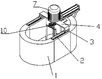
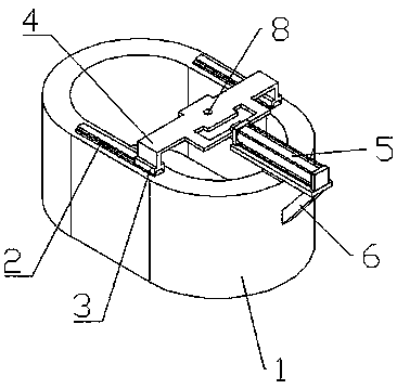
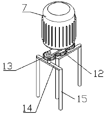
[0015] Such as Figure 1-4 As shown, a battery separator slurry tank stirring device includes a slurry tank 1, a slide rail 2, a sliding block 3, a support frame 4, a hydraulic cylinder 5, a bracket 6, a motor 7, a rotating hole 8, a rotating shaft 9, and a stirrer 10. , The slurry tank 1 has a semi-circular structure on both sides, linear slide rails 2 are provided on both sides of the top of the slurry tank 1, and the slide block 3 is slidably connected to the top of the slide rail 2, between the two slide blocks 3 A support frame 4 is fixed. The middle of the support frame 4 is vertically connected with a hydraulic cylinder 5, and the hydraulic cylinder 5 is fixed to one side of the slurry tank 1 through a bracket 6. The motor 7 is vertically arranged on the top of the support frame 4. 7 The rotating shaft 8 at the bottom end passes through the rotating h...


PUM


Abstract

The invention discloses a stirring device of a storage battery separation plate slurry tank. The stirring device comprises a slurry tank, sliding rails, sliding blocks, a supporting frame, a hydrauliccylinder, a bracket, a motor, a rotary hole, a rotary shaft and a stirrer, wherein two sides of the slurry tank are respectively of a semicircular structure; the linear sliding rails are arranged attwo sides of the top of the slurry tank; the sliding blocks are in sliding connection with the tops of the sliding rails; the supporting frame is fixed between the two sliding blocks; the hydraulic cylinder is vertically connected with the middle of the supporting frame; the hydraulic cylinder is fixed at one side of the slurry tank through the bracket; the motor is vertically arranged at the topof the supporting frame; the rotary shaft at the bottom end of the motor penetrates through the rotary hole in the middle of the supporting frame and is connected with the stirrer; the stirrer is arranged in the slurry tank. According to the stirring device disclosed by the invention, the stirring range and the stirring efficiency of the stirrer are increased, and the consumption power of the motor is saved.

Description

Technical field [0001] The invention relates to a stirring device, in particular to a battery separator slurry pool stirring device. Background technique [0002] In the process of making battery separators, it is necessary to fully stir ultra-fine glass fiber cotton, synthetic fibers, concentrated sulfuric acid and pure water. The internal volume of the stirring tank is large, and multiple motors are required to drive the stirring operation. Excessive motors consume a lot of power. The mixing tank has a rectangular structure, the liquid at the four corners of the slurry tank cannot be fully mixed, the mixing blades rotate in one direction, and the mixing efficiency is low, which requires further improvement. Summary of the invention [0003] The purpose of the present invention is to provide a battery separator slurry tank stirring device to solve the above technical problems. [0004] To achieve the above objectives, the present invention adopts the following technical solutions:...

Claims


Application Information

Patent Timeline
Patent Type & Authority Applications(China)
IPC IPC(8): B01F15/00B01F11/00
CPCB01F31/443B01F31/441B01F35/4111
Inventor 王浩王德友徐娜
Owner 枣庄市东昌玻纤实业有限公司
Why Eureka
Try Eureka