
Micropipettor based on automatic suction and transfer technology

A micropipette and technology, which is applied in the field of micropipettes, can solve the problems of limited and unsatisfactory taking accuracy, and achieve the effect of less human factors and high liquid taking accuracy.

Inactive Publication Date: 2019-01-01
郑州韦尔特生物科技有限公司
View PDF7 Cites 0 Cited by
  • Summary
  • Abstract
  • Description
  • Claims
  • Application Information

AI Technical Summary

Problems solved by technology

[0004] Traditional pipettes are mostly operated manually. Although there are scale marks on the pipette, due to irresistible factors such as line of sight deviation in human operation, the accuracy of the volume is limited, and it is difficult to meet the needs of the current stage.

Method used


Image

  • Micropipettor based on automatic suction and transfer technology
  • Micropipettor based on automatic suction and transfer technology
  • Micropipettor based on automatic suction and transfer technology

Examples


Embodiment 1

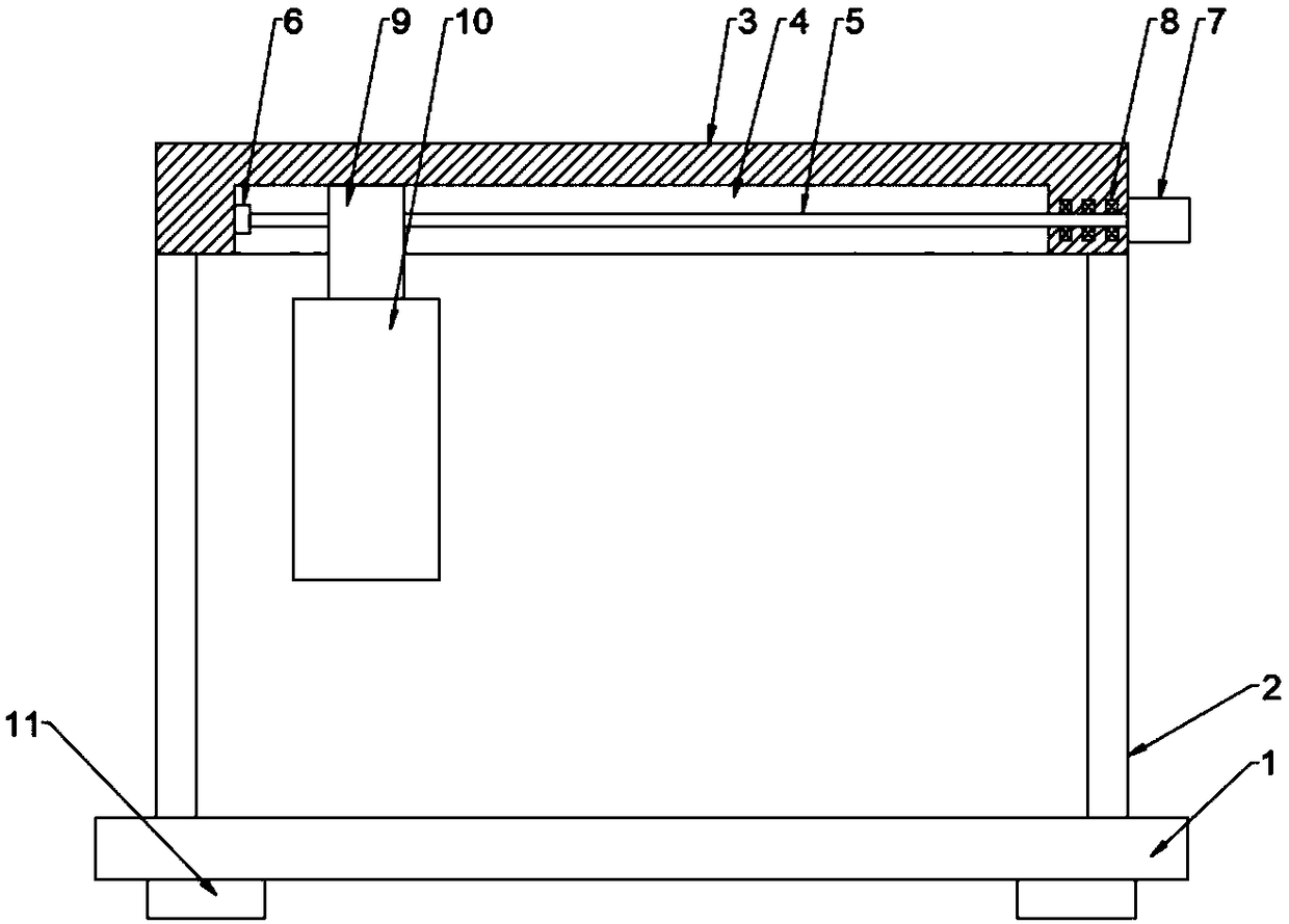
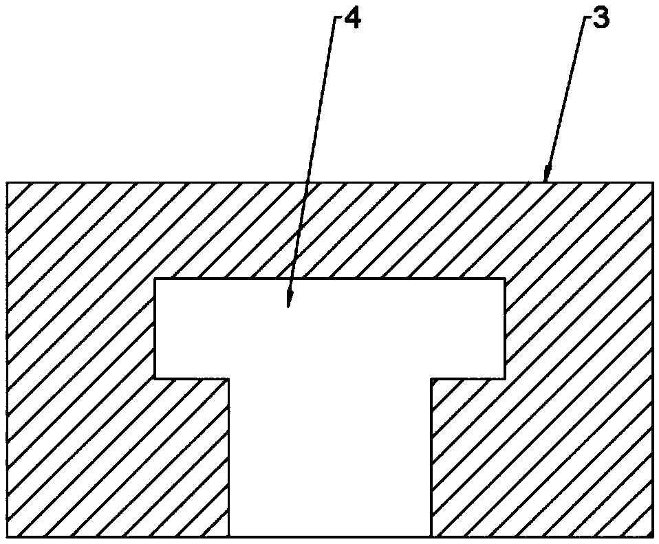
[0024] see Figure 1~3 , a micropipette based on automatic suction and transfer technology, comprising a base plate 1, a column 2, a beam 3 and a liquid-taking cylinder 10, the top surface of the base plate 1 is symmetrically provided with columns 2 on the left and right sides, and the two The top of column 2 is provided with crossbeam 3, and the bottom end of described crossbeam 3 is provided with chute 4, and described chute 4 is T-shaped groove, and the inner cavity of chute 4 is provided with screw mandrel 5, and chute 4 is connected with lead screw 5 are in a parallel relationship, one end of the screw 5 is rotatably connected to the inner cavity wall of the chute 4 through the bearing seat 6, and the other end of the screw 5 runs through the side end of the chute 4 and is fixedly connected to the motor 7 On the motor shaft, the motor 7 is fixedly connected to the crossbeam 3, the lead screw 5 is connected to the crossbeam 3 through the rotation of the bearing 8, the lead...

Embodiment 2

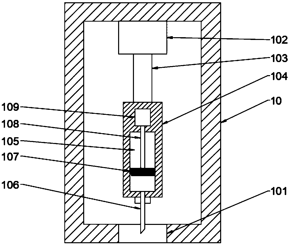
[0026] This embodiment is a further elaboration on the basis of Embodiment 1. A liquid-taking hole 101 is provided in the center of the bottom wall of the inner cavity of the liquid-taking cylinder 10, and a first electric telescopic Device 102, the bottom end of the first telescopic rod 103 on the first electric telescopic device 102 is fixedly connected with a liquid-taking column 104 matched with the liquid-taking hole 101, and the liquid-taking column 104 is a cylindrical structure, and the liquid-taking column 104 is a cylindrical structure. The axis of the column 104 coincides with the axis of the liquid-taking hole 101. The diameter of the liquid-taking column 104 is smaller than the diameter of the liquid-taking hole 101. A second electric telescopic device 109 and a liquid-taking cavity 105 are arranged in the liquid-taking column 104. The second electric telescopic device 109 is located above the liquid-taking chamber 105, and the bottom end of the second telescopic r...


PUM


Abstract

The invention discloses a micropipettor based on automatic suction and transfer technology. The micropipettor comprises a bottom plate, stand columns, a crossbeam and a liquid collection cylinder, wherein the left side and right side of the top end surface of the bottom plate are symmetrically provided with the stand column, the top ends of the two stand columns are respectively provided with thecrossbeam, the bottom end of the crossbeam is provided with a slide groove, an inner cavity of the slide groove is provided with a lead screw, one end of the lead screw is rotatably connected onto theinner cavity wall of the slide groove by virtue of a bearing seat, the other end of the lead screw penetrates through the side end of the slide groove and is fixedly connected onto a motor shaft of amotor, the motor is fixedly connected onto the crossbeam, the lead screw is rotatably connected onto the crossbeam by virtue of a bearing, the lead screw is sleeved with a movable seat matched with the slide groove, and the bottom end of the movable seat is provided with the liquid collection cylinder. The transfer work of the liquid collection cylinder is completed by utilizing the motor, the lifting of the liquid collection cylinder is completed by utilizing a first telescopic apparatus, the liquid collection and release work can be completed by utilizing a second electric telescopic apparatus, the liquid collection process and liquid release process as well as the liquid transfer process are automatically completed, the influence from the manual factor is slight, and the liquid collection precision is high.

Description

technical field [0001] The invention relates to the technical field of pipettes, in particular to a micropipette based on automatic suction and transfer technology. Background technique [0002] A pipette, also known as a pipette gun, is an instrument for quantitatively transferring liquids and is widely used in biology, chemistry and other fields. Micropipette is an essential tool for biochemical experiments or molecular biology experiments. [0003] A micropipette is a precision liquid-taking device (commonly known as a gun) that can be adjusted at will within a certain capacity range. The basic principle is to rely on the up and down movement of the piston in the device, and the moving distance of the gas piston is realized by the adjustment wheel to control the screw structure. , push the button to drive the push rod to move the piston down to remove the gas in the piston chamber. After letting go, the piston returns to its original position under the action of the ret...

Claims


Application Information

Patent Timeline
Patent Type & Authority Applications(China)
IPC IPC(8): B01L3/02
CPCB01L3/0203B01L2400/0478
Inventor 李博文
Owner 郑州韦尔特生物科技有限公司
Learn More