
High-efficiency disassembling tool for inner ring of bearing

A technology for bearing inner rings and disassembly tooling, which is applied in the direction of manufacturing tools and hand-held tools, etc., can solve the problems of large axial size of disassembly tooling, low disassembly efficiency, and high manufacturing cost, and achieves simple structure, low processing cost, and guaranteed structure The effect of intensity

Pending Publication Date: 2019-01-01
株洲九方装备驱动技术有限公司 +1
View PDF0 Cites 5 Cited by
  • Summary
  • Abstract
  • Description
  • Claims
  • Application Information

AI Technical Summary

Problems solved by technology

However, the bearing dismounting tooling in the prior art is carried by the end face of the axle, which has low disassembly efficiency, heavy tooling weight, large space occupation, and high manufacturing cost. It is more suitable for dismounting the bearing where the bearing installation position is close to the axle end face. When the location is far from the axle end face, longer connecting parts are required, and the overall axial dimension of the disassembly tool is large, heavy, and takes up a lot of space; when the distance between the bearings of different types of gearboxes and the axle end face is different, different sizes need to be made connection parts, high manufacturing cost and low versatility

Method used


Image

  • High-efficiency disassembling tool for inner ring of bearing
  • High-efficiency disassembling tool for inner ring of bearing
  • High-efficiency disassembling tool for inner ring of bearing

Examples


Embodiment 1

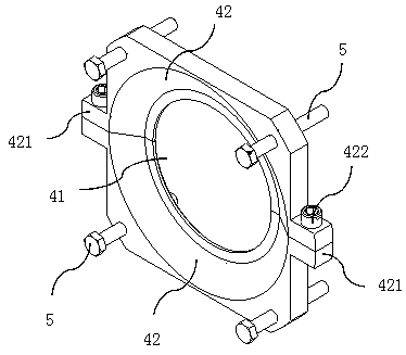
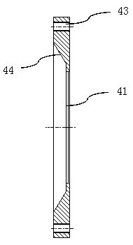
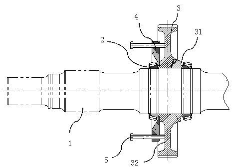
[0022] Such as figure 1 with image 3 As shown, an efficient disassembly tool for bearing inner ring is provided, which is applied to the disassembly of the bearing on the shaft, and is especially suitable for the dismantling of the bearing inner ring 2 on the axle 1 in the rail transit car material gear box. The axle 1 is installed close to the bearing. There is a gear 3, and the disassembly tool includes a closed disassembly ring 4 with an inner hole 41 formed by connecting two sub-disassembly rings 42 with the same structure in sequence. The gear 3 is provided with a circumferential groove 31 for closing the disassembly ring at the installation and joint of the bearing 2 4 The embedded and embedded closed and disassembled ring 4 The first end face is attached to the end face of the bearing inner ring 2 and the second end face is attached to the side wall of the upper circumferential groove 31 of the gear. The inner hole wall of the closed and disassembled ring 4 is attached t...


PUM


Abstract

The invention belongs to the technical field of tool equipment, and discloses a high-efficiency disassembling tool for an inner ring of a bearing. The high-efficiency disassembling tool for the innerring of the bearing is applied to disassembling the bearing on a shaft; a gear is arranged on the shaft; the disassembling tool comprises a closed disassembling ring provided with an inner hole and formed by sequentially connecting multiple sub disassembling rings; a circumferential groove is formed at the position, installed and combined with the bearing, of the gear so as to be used for the closed disassembling ring to embed; the first end surface of the embedded closed disassembling ring fits to the end surface of the inner ring of the bearing; the second end surface of the embedded closeddisassembling ring fits to the side wall of the circumferential groove in the gear; the inner hole wall of the closed disassembling ring fits to the groove bottom of the circumferential groove; and multiple ejection mechanisms capable of being abutted against a gear web so as to enable the closed disassembling ring to drive the bearing to separate and displace along the axial direction of the shaft are uniformly distributed on the circumferential direction of the closed disassembling ring. The multiple sub disassembling rings are combined into the closed disassembling ring, the inner ring of the bearing can be easily returned to the position on which the inner ring of the bearing can be easily taken out through the ejection mechanisms abutted against the gear web so as to enable the innerring of the bearing to separate, and the tool can adapt to disassembling bearings under different conditions of various bearing installation position.

Description

Technical field [0001] The invention relates to the technical field of tooling equipment, in particular to a tool for efficiently disassembling a bearing inner ring. Background technique [0002] Bearing is an important component in the mechanical field, which is composed of inner ring, outer ring, rolling element and cage. When the bearing is not installed properly, regular maintenance and other situations, it needs to be disassembled. Since interference fit is often used between the inner ring of the bearing and the shaft parts, it is difficult to dismount the bearing when it is disassembled to ensure that the bearing is not damaged. [0003] The general methods used to disassemble the bearing are directly knocking out, heating and using tooling. Direct knocking is very easy to damage the bearing, especially when the inner ring of the bearing and the shaft have a large amount of interference, it is very difficult to knock out directly; the heating method needs to control the te...

Claims


Application Information

Patent Timeline
Patent Type & Authority Applications(China)
IPC IPC(8): B25B27/06
CPCB25B27/062
Inventor 陈宇向姚建辉刘领化潘喻
Owner 株洲九方装备驱动技术有限公司
Learn More