
Electro-hydraulic compound movable arm energy recovery system

An energy recovery, electro-hydraulic composite technology, applied in the direction of earth mover/shovel, construction, etc., can solve the problem of low energy utilization rate, reduce energy consumption, avoid energy recovery and reuse conversion links, reduce power output effect

Inactive Publication Date: 2019-01-01
HUAQIAO UNIVERSITY
View PDF8 Cites 4 Cited by
  • Summary
  • Abstract
  • Description
  • Claims
  • Application Information

AI Technical Summary

Problems solved by technology

[0004] The purpose of the present invention is to overcome the deficiencies of the prior art, and avoid the disadvantages of low energy utilization rate caused by the energy recovery and reuse conversion links of the traditional electric energy recovery system

Method used


Image

  • Electro-hydraulic compound movable arm energy recovery system

Examples


Embodiment

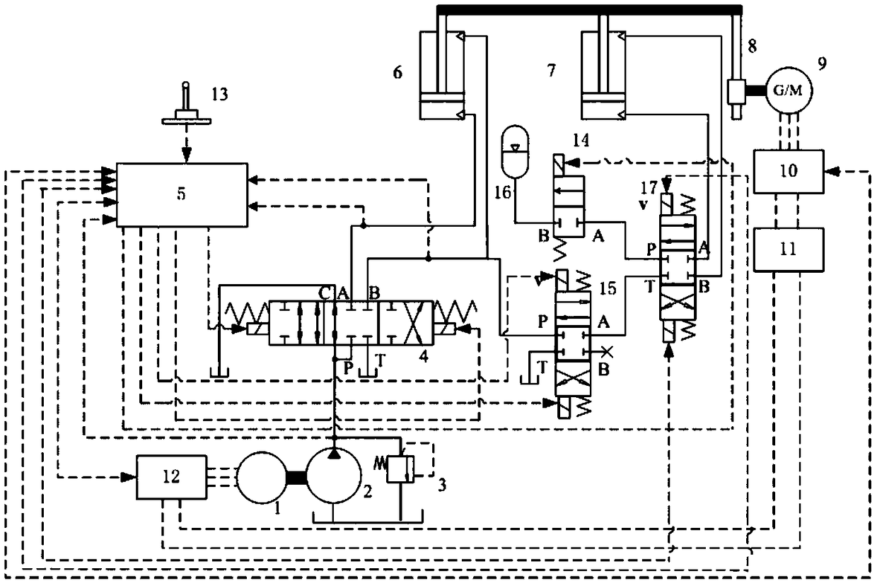
[0021] The patent of the present invention will be further described below in conjunction with the accompanying drawings and specific embodiments.

[0022] refer to figure 1 ,

[0023] (1) Boom down energy recovery:

[0024] When the boom pilot control handle 13 is in the lowering position of the boom, the controller 5 outputs a signal at this time to connect the control oil circuit on the right side of the multi-way valve 4 to high-pressure oil, so that the multi-way valve 4 is in the right position to work. At this time, its oil Port P communicates with B, and oil port A communicates with oil port T. The controller 5 issues speed control instructions to the motor controller 12, and the motor 1 drives the hydraulic oil output by the hydraulic pump 2 to enter the upper chamber of the original driving cylinder 6 and the balance cylinder 7 of the boom, that is, the rod chamber, and the original driving cylinder 6 and The lower chamber of the balance oil cylinder 7, that is, t...


PUM


Abstract

The invention provides an electro-hydraulic compound movable arm energy recovery system. A balance oil cylinder piston is connected with an electric / generator through a linear rotating motion pair; and the relative positions of a balance oil cylinder drum and the electric / generator are maintained invariable. When a movable arm is descended, high-pressure oil in a rodless cavity of a balance oil cylinder flows into a hydraulic energy storer, and part of potential energy and kinetic energy in the descending process of the movable arm are converted as hydraulic energy for storage; and meanwhile,the balance oil cylinder piston drives the motion pair to move, and the motion pair drives part of the potential energy and the kinetic energy of the movable arm to convert as the electric energy forstorage in an electric energy storage unit. When the movable arm is ascended, the high-pressure oil in the hydraulic energy storer flows into the rodless cavity of the balance oil cylinder to drive amovable arm piston to ascend; and meanwhile, the electric / generator sucks the electric energy from the electric energy storage unit to drive the motion pair to rotate to drive the piston of the balance oil cylinder to ascend for balancing the weight of part of the movable arm and loads and driving the movable arm to ascend with an original driving oil cylinder, so that the output energy of a hydraulic pump is reduced.

Description

technical field [0001] The invention relates to an energy recovery system, in particular to an electro-hydraulic composite boom energy recovery system. Background technique [0002] With the development of society, problems such as air pollution and energy shortage have become increasingly prominent. In order to improve air quality and energy efficiency, many international organizations and institutions have introduced strict regulations on engine exhaust emissions, and various government departments have advocated the development and promotion of energy-saving and emission-reduction technologies. As a typical construction machine, hydraulic excavators are widely used in construction, coal mines, and water conservancy fields. However, due to their low efficiency and high emissions, they have attracted great attention from industry and academia. At present, a lot of research work has been carried out on the energy-saving technology of excavators at home and abroad. Among th...

Claims


Application Information

Patent Timeline
Patent Type & Authority Applications(China)
IPC IPC(8): E02F9/00E02F9/22
CPCE02F9/00E02F9/2217
Inventor 陈其怀林添良任好玲付胜杰缪骋吕若曦
Owner HUAQIAO UNIVERSITY
Learn More