Military unmanned aerial vehicle mounting system

A mounting system and unmanned aerial vehicle technology, which is applied in the field of military unmanned aerial vehicle mounting system, can solve the problem of inability to meet the mounting requirements of various cruise tasks, the inconvenient position adjustment of mounting equipment, and the inability to mount multiple devices at the same time and other issues, to achieve the effect of ensuring stability and maneuverability, improving capability and flight quality, and simple structure

Inactive Publication Date: 2019-09-06
杭州木书科技有限公司
View PDF8 Cites 5 Cited by
  • Summary
  • Abstract
  • Description
  • Claims
  • Application Information

AI Technical Summary

Problems solved by technology

[0004] The purpose of the present invention is to solve the problems in the prior art that multiple devices cannot be mounted at the same time, and the assembly of the devices is relatively complicated, it is not easy to disassemble and assemble, and it is inconvenient to adjust the position of the mounted devices, which cannot meet the mounting requirements of various cruising tasks. The shortcomings of the proposed military UAV mounting system

Method used


Image

  • Military unmanned aerial vehicle mounting system
  • Military unmanned aerial vehicle mounting system
  • Military unmanned aerial vehicle mounting system

Examples


Embodiment 1

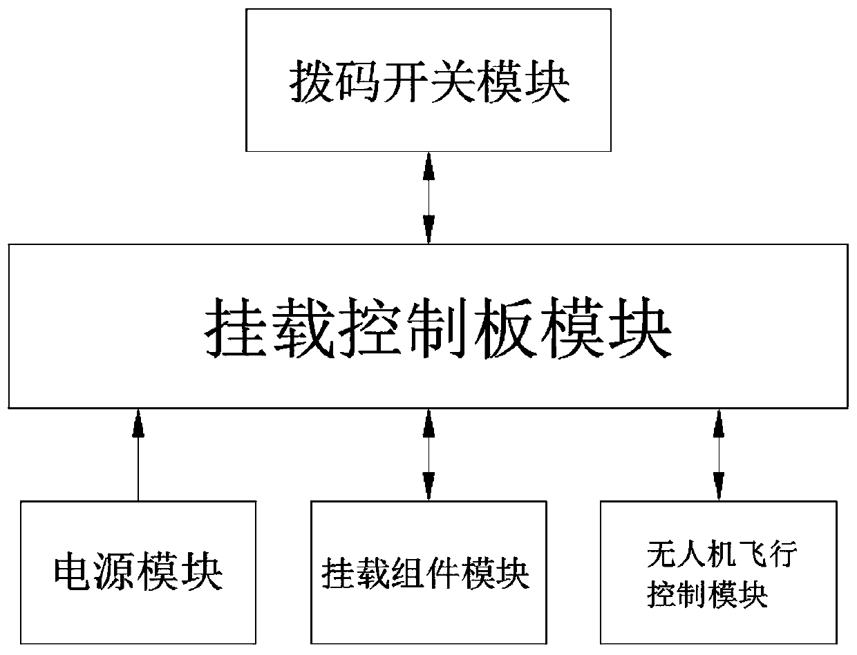
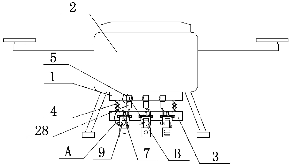
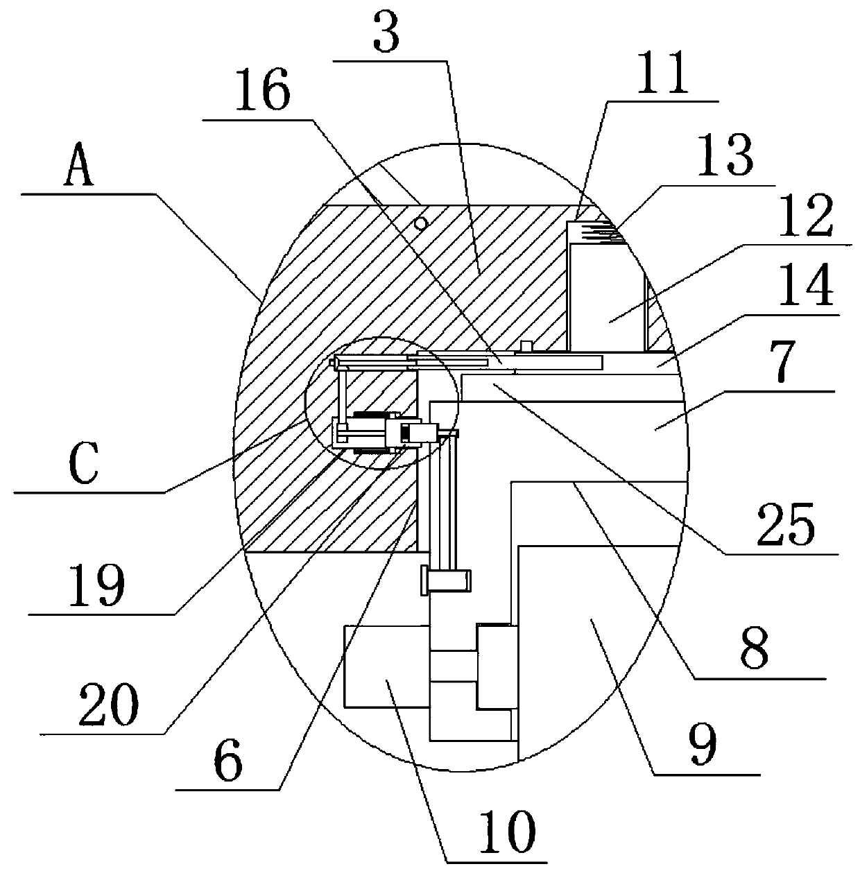
[0025] refer to Figure 1-5 , a military UAV mounting system, including a dial switch module, a mount control board module, a power supply module, a mount component module and a UAV flight control module, the dial switch module is connected to the mount control board module , the power module is connected to the mount control board module, the mount control board module is connected to the mount component module, the UAV flight control module is connected to the mount component module, and the mount control board module includes mount general board 1 The UAV body 2 is fixedly mounted on the top of the mounting universal board 1, the mounting plate 3 is mounted on the bottom of the mounting general board 1, and two telescopic folding rods 4 are fixedly mounted on the top of the mounting board 3, and the two telescopic folding rods The tops of 4 are all fixedly installed on the bottom of the mounting universal board 1, and the bottom of the mounting universal board 1 is provided...

Embodiment 2

[0035] refer to Figure 1-5 , further improvements have been made on the basis of Example 1:

[0036] A military unmanned aerial vehicle mounting system includes a dial switch module, a mount control board module, a power supply module, a mount component module and a flight control module of the drone, and the dial switch module is connected with the mount control board module, The power module is connected to the mount control board module, the mount control board module is connected to the mount component module, the UAV flight control module is connected to the mount component module, and the mount control board module includes mount general board 1, The top of the mounting plate 1 is fixed with the drone body 2 by bolts, the bottom of the mounting plate 1 is provided with an assembly plate 3, and the top of the assembly plate 3 is fixed with two telescopic folding rods 4, two The tops of the telescopic folding rods 4 are all fixedly installed on the bottom of the mounting...


PUM


Abstract

The invention belongs to the field of military unmanned aerial vehicles, and particularly discloses a military unmanned aerial vehicle mounting system. The military unmanned aerial vehicle mounting system solves the problems that at present, a plurality of devices cannot be mounted at the same time, equipment assembly is complicated, disassembly is not convenient, and mounting equipment has inconvenient position adjustment, and is unable to meet the mounting requirements of a variety of cruise missions. According to a following scheme, the military unmanned aerial vehicle mounting system includes a dial switch module, a mounting control board module, a power module, a mounting component module and an unmanned aerial vehicle flight control module, wherein the dial switch module is connectedto the mounting control board module, the power module is connected to the mounting control board module, and the mounting control board module is connected to the mounting component module. The military unmanned aerial vehicle mounting system has a simple structure and convenient operation, can mount the multiple devices at the same time, and facilitates installation and disassembly of the devices, the mounting equipment is convenient to be subjected to position adjustment, and the mounting requirements of a variety of cruise missions can be met.

Description

technical field [0001] The invention relates to the technical field of military unmanned aerial vehicles, in particular to a military unmanned aerial vehicle mounting system. Background technique [0002] At present, with the development of science and technology, the application range of drones is becoming more and more extensive. Institutions and units such as power departments, public security departments, traffic police departments, land surveying and mapping, film and television photography, and live news broadcasts have successively purchased drones to solve the problems of various departments. For various needs, military UAVs mostly use multi-rotor four-axis UAVs as a carrier. Its use depends on the mounting modules of the UAV. Different modules can be mounted to complete different tasks. Mounting infrared cameras can complete tasks such as power line inspection, and mounting remote sensing equipment can complete surveying and mapping tasks; [0003] However, there a...

Claims


Application Information

Patent Timeline
Patent Type & Authority Applications(China)
IPC IPC(8): B64D47/00
CPCB64D47/00B64U2101/00B64U10/10
Inventor 徐志勇吴子霖玄宇轩
Owner 杭州木书科技有限公司
Why Eureka
Try Eureka