Time-of-arrival detection device and method and positioning device

A detection device and time-of-arrival technology, which is used in measurement devices, positioning, radio wave measurement systems, etc., can solve the problem that it cannot reach close to ninety degrees, the positioning system cannot provide accurate positioning signal arrival time measurement standards, and affects positioning accuracy, etc. question

Pending Publication Date: 2019-01-01
KUNCHEN TECH CO LTD
View PDF0 Cites 6 Cited by
  • Summary
  • Abstract
  • Description
  • Claims
  • Application Information

AI Technical Summary

Problems solved by technology

Ideally, the rising edge of the UWB pulse can reach close to 90 degrees. At this time, the arrival time measured by the above method is more accurate, but in the actual scene, due to the limitation of hardware equipment, the rising edge of the UWB pulse cannot reach close to 90 degrees. Ten degrees, at this time, setting different amplitude thresholds will result in different positioning signal arrival

Method used


Image

  • Time-of-arrival detection device and method and positioning device
  • Time-of-arrival detection device and method and positioning device
  • Time-of-arrival detection device and method and positioning device

Examples


Embodiment Construction

[0015] Specific embodiments of the present invention will be described in detail below, and it should be noted that the embodiments described here are only for illustration, not for limiting the present invention. In the following description, numerous specific details are set forth in order to provide a thorough understanding of the present invention. It will be apparent, however, to one of ordinary skill in the art that these specific details need not be employed to practice the present invention. In other instances, well-known circuits, materials or methods have not been described in detail in order to avoid obscuring the present invention.

[0016] Throughout this specification, reference to "one embodiment," "an embodiment," "an example," or "example" means that a particular feature, structure, or characteristic described in connection with the embodiment or example is included in the present invention. In at least one embodiment. Thus, appearances of the phrases "in on...


PUM


Abstract

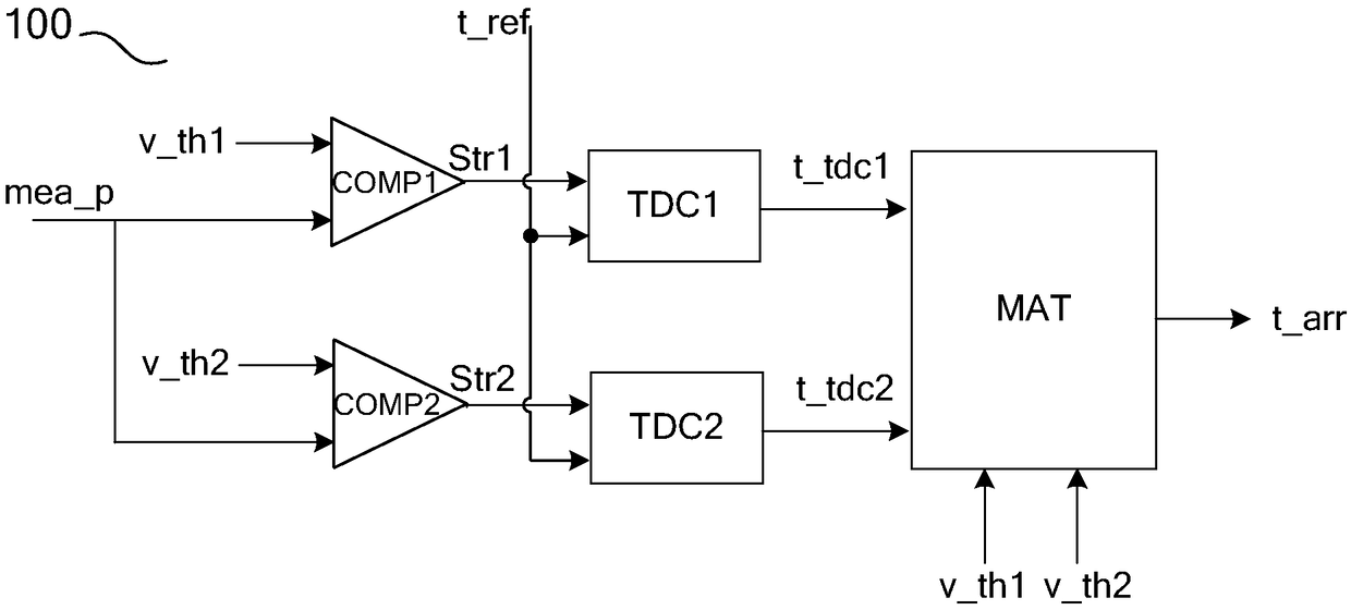
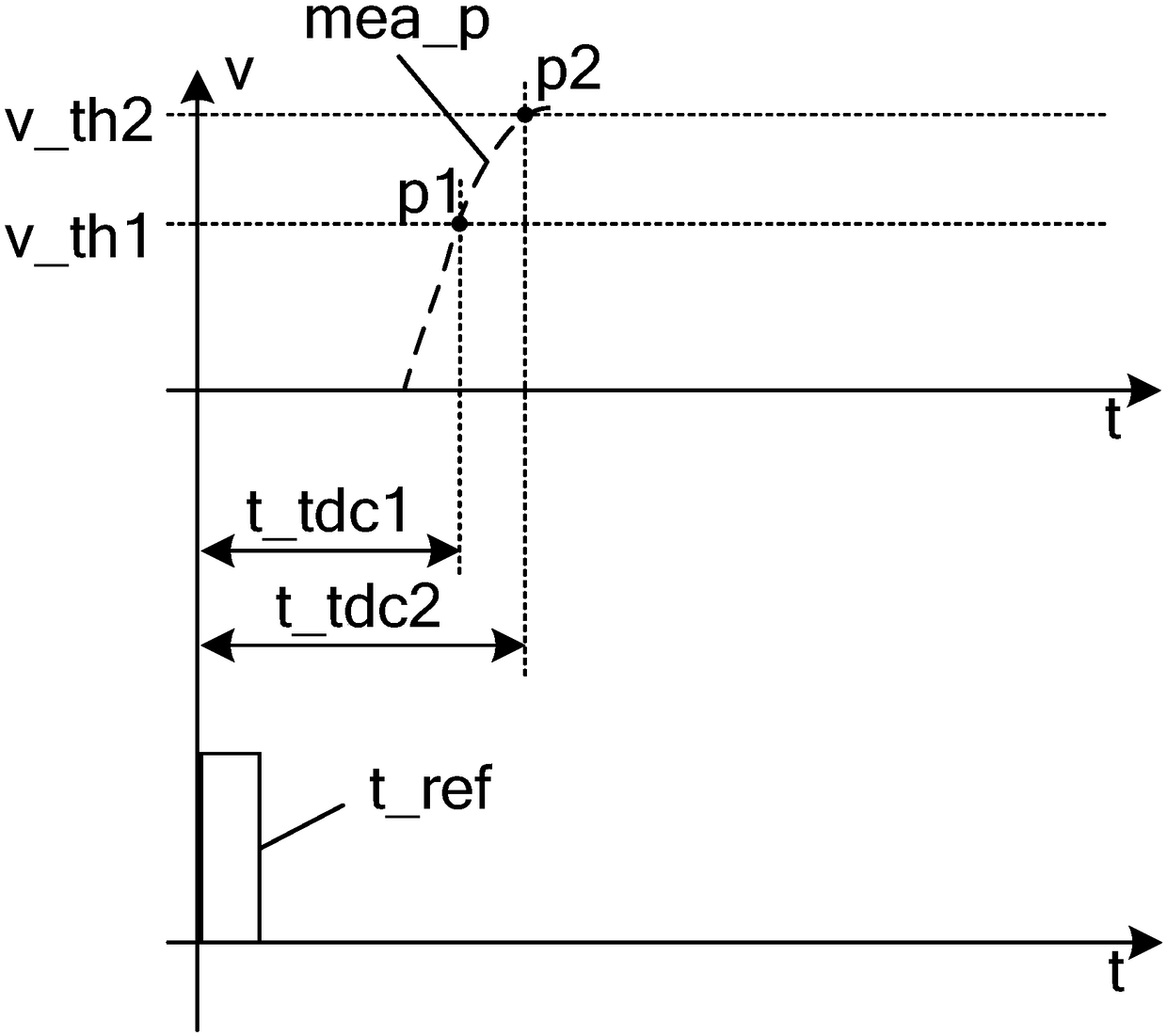
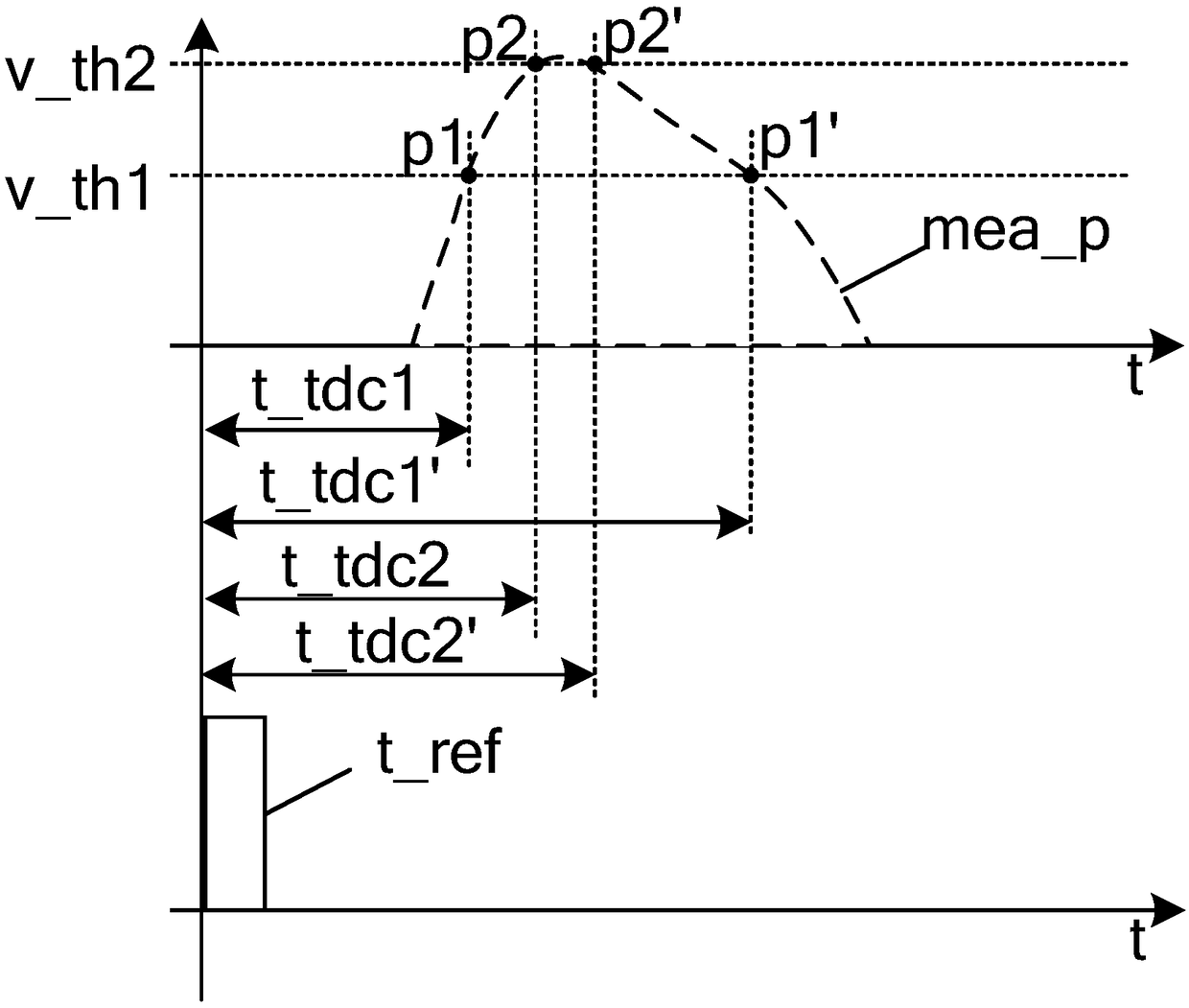
The invention discloses a time-of-arrival detection device and method. By setting multiple comparison circuits and time-to-digital conversion circuits in the time-of-arrival detection device, receivedpulse signals are sampled at multiple points, the envelope of the pulse signals is fitted out, and the envelope is matched with pre-stored pulse envelopes to identify the received pulse signals as useful signals or interference signals. Furthermore, a reference point is set according to the matching result, and the time of arrival or the time-of-arrival difference of the pulse signals is obtainedaccurately by measuring the time values of the reference point on a pulse signal transmitting envelope and the pulse signal receiving envelopes of the time-of-arrival detection device and other time-of-arrival detection devices. The technical problem that interference signals cannot be excluded in a single comparison circuit and time-to-digital conversion circuit and the technical problem that the time of arrival of a pulse signal cannot be determined accurately due to the fluctuation of the amplitude of the pulse signal in the prior art are solved.

Description

technical field [0001] The invention relates to the field of wireless communication, in particular to time measurement in a positioning system. Background technique [0002] For the safety monitoring of large buildings, urban dense areas, bridges, dams, mountains, foundation pits and other areas, it is helpful to realize the safety monitoring of personnel, emergency rescue, transportation management, distribution and scheduling of materials, and natural disasters prevention and monitoring, etc. Due to dense buildings, occlusion, and complex environment, the monitoring space is narrow and GPS and Beidou signals often cannot be covered deeply, which makes space monitoring difficult. In the prior art, the positioning and monitoring of a designated target in a specific area is realized through a self-built positioning system. UWB (Ultra Wideband) is a carrier-free communication technology that uses nanosecond to picosecond non-sinusoidal narrow pulses to transmit data. UWB ha...

Claims


Application Information

Patent Timeline
IPC IPC(8): G01S5/06G01S11/02
CPCG01S5/06G01S11/02
Inventor 黄伟朱晓章叶加伟张晨曦李飞雪
Owner KUNCHEN TECH CO LTD
Why Eureka
Try Eureka