
Signal processing method for in-situ, scanned-beam particle monitoring

a particle monitor and signal processing technology, applied in the field of semiconductor wafer processing, can solve the problems of particle depositing on a processed wafer that cannot be measured with the sensor in the pump-line configuration, and the ispm sensor application often produces poor correlation with the number of particles, so as to reduce the number of false negatives and better determine the existence of single pulse events

Inactive Publication Date: 2005-06-14
INFICON INC
View PDF86 Cites 5 Cited by
  • Summary
  • Abstract
  • Description
  • Claims
  • Application Information

AI Technical Summary

Benefits of technology

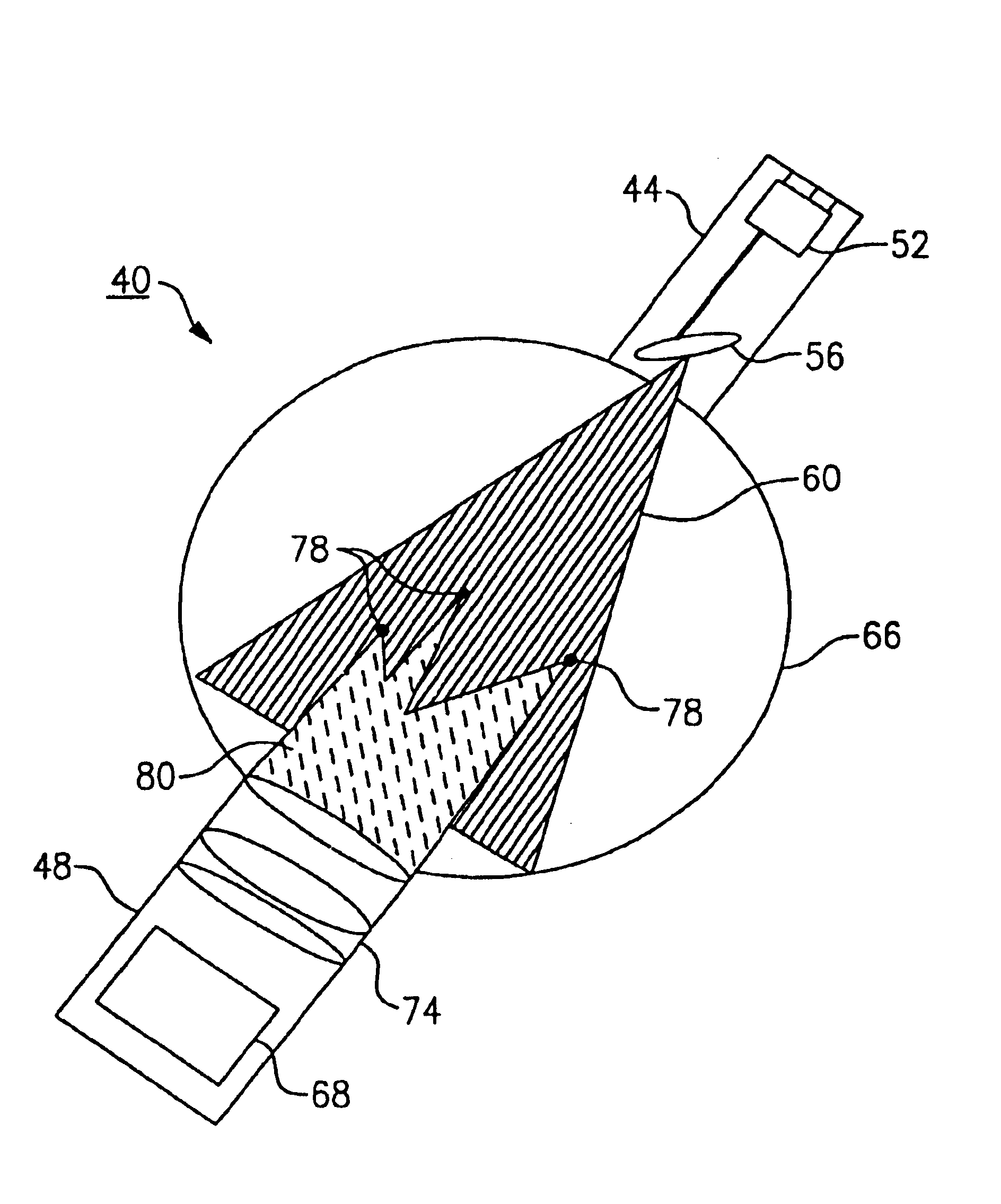
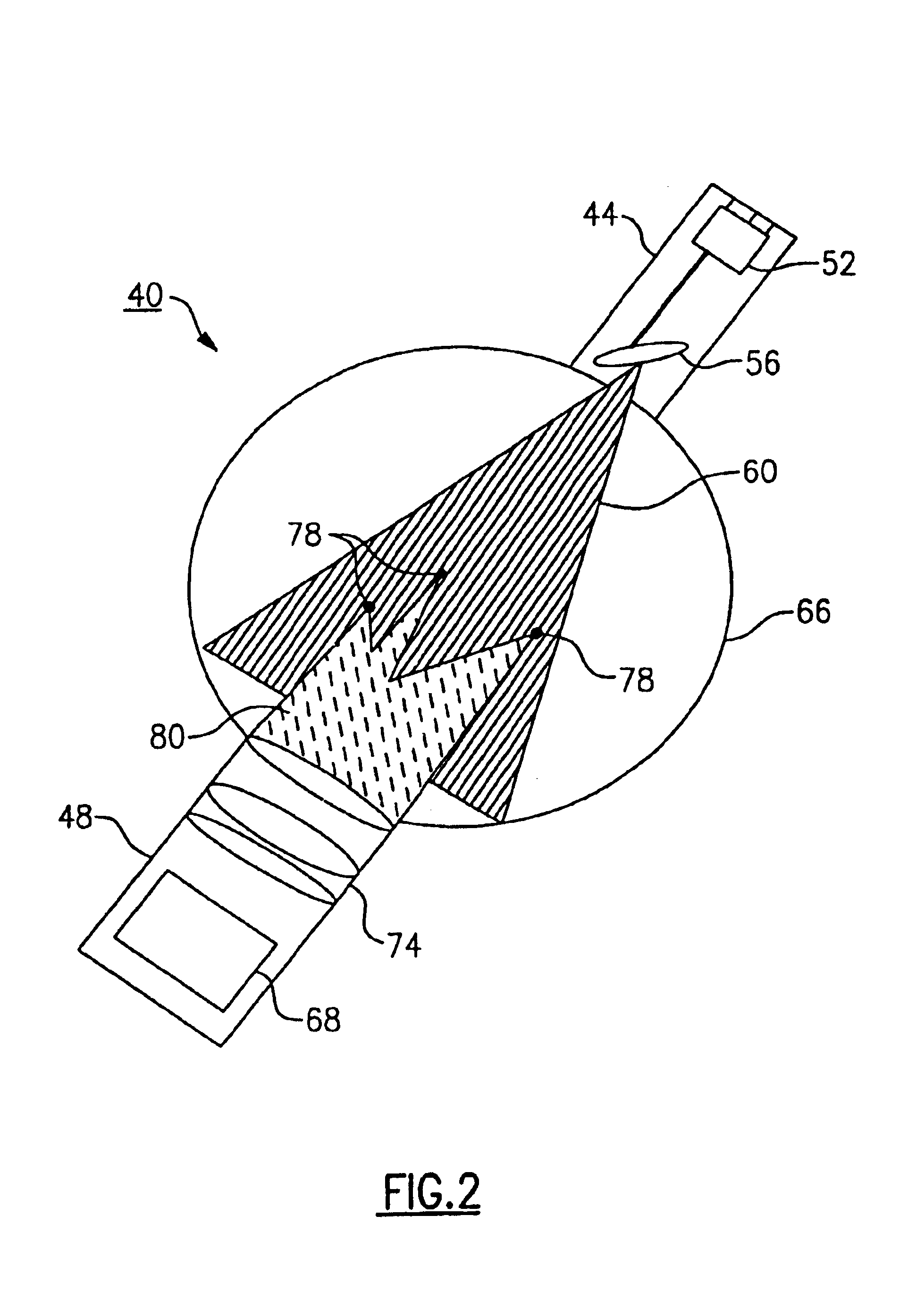
[0008]It is another primary object of the present invention to eliminate or substantially reduce the incidence of false negatives occurring in a measurement volume using a scanning light source / detection apparatus.
[0013]Preferably, and in practice, the light pulse that is scattered by each scanned particle crossing through the measurement volume is initially detected by a photo-multiplier. The electrical current output from the photo-multiplier is then converted by conventional means into a voltage pulse, which is subsequently amplified such as for example, by means of a high-speed, two stage analog amplifier. A level-triggering device, such as a discriminator, eliminates those signals that do not exceed a minimum threshold value.
[0015]The signal processing method of the present invention is comprised of three primary functions: 1) noise removal through analysis in the time domain; 2) identification of particle-pulse envelopes (PPEs) through forward and reverse autocorrelation; and 3) Gaussian fitting to each particle-pulse envelope for particle size and speed estimates. PPE identification through forward and reverse autocorrelation is particularly important since it facilitates identification of singular particle scattering events. Achieving these count statistics is a primary objective of AWISPM sensor measurement.
[0020]According to a preferred version of the invention, it has also been learned that by setting the discrimination level to at least three times and preferably four times the level of background noise will significantly reduce the number of false negatives that are detected which is essential to better determine the existence of single pulse events (e.g., particles which are contacted only a single time by the scanned beam).

Problems solved by technology

However, there are several inherent disadvantages to pump-line installation of a sensor apparatus.
First, a particle depositing on a processed wafer cannot be measured with the sensor in the pump-line configuration.
Second, and because ISPM sensors depend on various particle transport mechanisms to detect the particles generated upstream in the process chamber, ISPM sensor applications often produce poor correlation with the number of particles that deposit directly on the product wafer surface.
In addition, the particle detection volume for ISPM sensors is also limited by the small cross-sectional area of the laser beam which is illuminating the particle (s).

Method used


Image

  • Signal processing method for in-situ, scanned-beam particle monitoring
  • Signal processing method for in-situ, scanned-beam particle monitoring
  • Signal processing method for in-situ, scanned-beam particle monitoring

Examples


Embodiment Construction

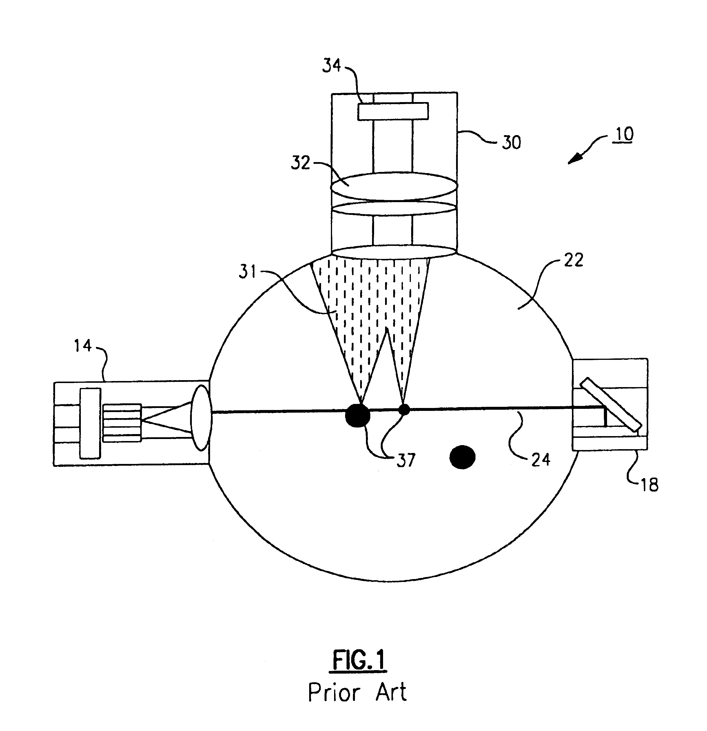
[0033]Referring to FIG. 1, there is shown an ISPM (in situ Particle Measurement) system in accordance with the prior art. The system 10 includes a laser diode 14 which emits a fixed collimated light beam 24 across a measurement volume, such as a pump line 22. A beam dump 18 disposed oppositely from the laser diode 14 is used to collect the resulting light beam 24 in order to minimize background light. Particles 37 crossing the measurement volume cause the light beam 24 to back, forward or side scatter with the resulting light 31 being detected by an orthogonally arranged detector assembly 30 having a photocell 34 which receives focused scattered light through an collection optical system 32. Peak detection is employed on resulting voltage spikes from the scattered fixed beam to count particles over a preset threshold. As note, the light beam of the above ISPM system is fixed; therefore, the light beam can only impinge upon a particle moving through the measurement volume a single ti...


PUM


Abstract

A novel method for analyzing the pulse train resulting from a scanned beam particle monitor is described. The method enhances signal-to-noise ratio and significantly reduces particle false alarm rate. Performed in the time domain, the method filters noise pulses that do not occur at the scanner frequency. The analysis further identifies particle-pulse-envelopes (PPE's) by performing a forward-looking and backward-looking autocorrelation. Gaussian fits are subsequently applied to identified particle-pulse envelopes, to determine particle characteristics, such as size and speed.

Description

[0001]This application claims priority upon a provisional patent application, application Ser. No. 60 / 318,073, filed Sep. 7, 2001.FIELD OF THE INVENTION[0002]This invention relates to the field of semiconductor wafer processing, and more particularly to a method for analyzing the signals resulting from a scanned beam particle monitor.BACKGROUND OF THE INVENTION[0003]In-situ particle monitoring (ISPM) sensors can provide continuous monitoring of particulate contamination levels during key semiconductor process operations. Based upon light-scattering detection techniques, ISPM sensors are typically installed downstream of the process chamber, such as to a pump-line, and provide real-time measurement of variations in particle concentration and size during wafer processing. However, there are several inherent disadvantages to pump-line installation of a sensor apparatus. First, a particle depositing on a processed wafer cannot be measured with the sensor in the pump-line configuration. ...

Claims


Application Information

Patent Timeline
IPC IPC(8): G01N15/02G01N15/00G01N15/06
CPCG01N15/0211G01N2015/0216H01L22/00
Inventor BONIN, MICHEL P.STIBBICH, AARONHOLVE, DONALD J.
Owner INFICON INC
Learn More