
Optical fiber transmission system with transmission coefficient self-calibration function and using method thereof

A technology of transmission system and transmission coefficient, which is applied in the field of optical fiber transmission system, can solve the problems of output optical power reduction, transmission coefficient change, transmission coefficient and transmission coefficient inconsistency, etc., and achieve the effect of improving accuracy

Active Publication Date: 2019-01-01
卢小丽
View PDF5 Cites 1 Cited by
  • Summary
  • Abstract
  • Description
  • Claims
  • Application Information

AI Technical Summary

Problems solved by technology

However, in the actual use process, the luminous efficiency of the semiconductor laser inside the optical fiber transmission system is greatly affected by the change of the external temperature. The specific performance is that as the temperature rises, the luminous efficiency of the laser decreases, and the output optical power decreases, resulting in a lower transmission coefficient in actual use. Inconsistent with the calibrated transfer coefficient
In addition, changing the optical fiber and the tightness of the optical fiber interface is different from that in the calibration state, which will also lead to changes in the transmission coefficient, resulting in measurement errors

Method used


Image

  • Optical fiber transmission system with transmission coefficient self-calibration function and using method thereof
  • Optical fiber transmission system with transmission coefficient self-calibration function and using method thereof
  • Optical fiber transmission system with transmission coefficient self-calibration function and using method thereof

Examples


Embodiment Construction

[0047] The present invention will be described in further detail below in conjunction with the accompanying drawings.

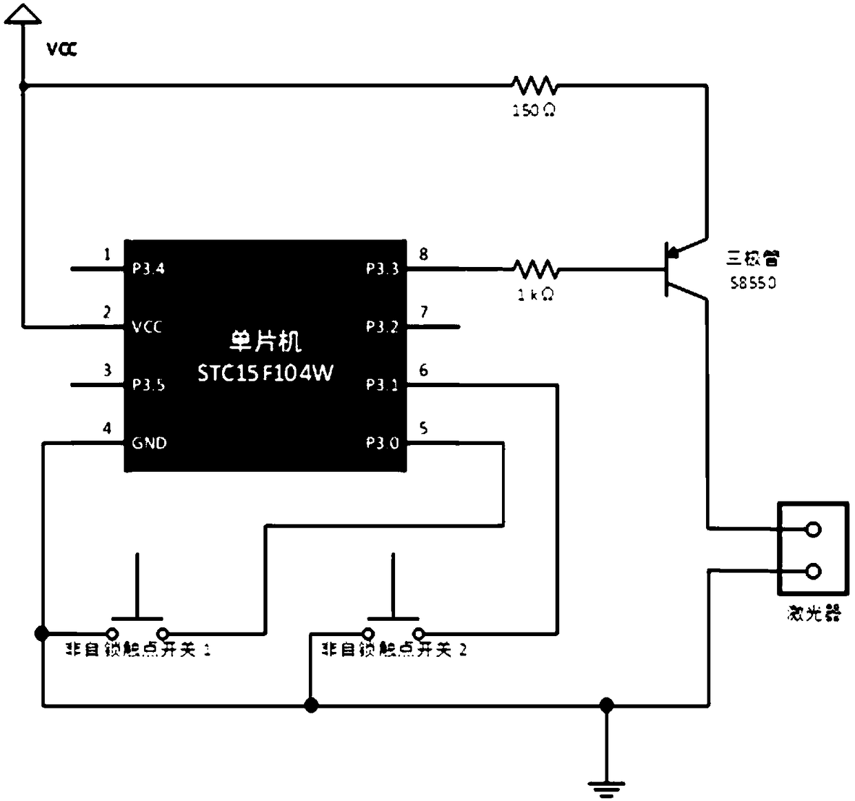
[0048] In terms of function, it includes two parts: the measurement channel and the control channel; the measurement channel adopts open technology, such as Figure 6 As shown, the basic function of optical fiber transmission is realized; the present invention realizes the self-calibration function of the transmission coefficient of the optical fiber transmission system through the control path.

[0049] In terms of composition, the optical fiber transmission system is still divided into two parts, the front end and the back end, such as figure 1 shown. The front end and the back end of the transmission system need to be connected by two optical fibers, the optical fiber 1 is used for the measurement path, and the optical fiber 2 is used for the control path.

[0050] After adding the self-calibration function to the optical fiber transmission system, the c...


PUM


Abstract

The invention relates to an optical fiber transmission system with a transmission coefficient self-calibration function and a using method thereof. The optical fiber transmission system with a transmission coefficient self-calibration function includes a front end of the transmission system and a back end of the transmission system, wherein the front end of the transmission system includes a frontend input circuit, an integration circuit, an amplifying circuit, an electro-optical conversion circuit, an electro-optical conversion circuit, a control signal response circuit and a standard squarewave generating circuit; the back end of the transmission system includes a photoelectric conversion circuit, an amplifying circuit, an output circuit, a photoelectric conversion circuit, a switch control circuit, a control signal generating circuit and an electro-optical conversion circuit; in a laboratory, by comparing the amplitude of an output electrical signal of the optical fiber transmission system with the amplitude of an input electrical signal of the optical fiber transmission system, a transmission coefficient S0 of the optical fiber transmission system is obtained, and an output amplitude U0 of the standard square wave is recorded during the process that the standard square wave is transmitted to the back end from the front end through the electro-optical-photoelectric conversion; in actual use, the output amplitude U1 of the standard square wave in the current state is read; and the system transmission coefficient S1 = S0*(U1 / U0) in the current test state. The optical fiber transmission system with a transmission coefficient self-calibration function improves the transmission accuracy of electrical signals passing the fiber optic transmission system.

Description

technical field [0001] The invention relates to the technical field of electromagnetic environment effect measurement, in particular to an optical fiber transmission system with a transmission coefficient self-calibration function and a use method. Background technique [0002] In the field of measurement such as electromagnetic environment effect test, it is often necessary to measure parameters such as the coupling current of the cable. In order to avoid the long-distance transmission attenuation of the electrical signal responded by the coupling current sensor and the like or being interfered by the electromagnetic environment, it is often necessary to use optical fiber transmission. The system converts certain measurement signals from electro-optic to photoelectric, and transmits the signals to the remote shielding room by means of optical fiber transmission, so as to realize the measurement and recording of signals. [0003] Before using the optical fiber transmission s...

Claims


Application Information

Patent Timeline
Patent Type & Authority Applications(China)
IPC IPC(8): H04B10/079H04B10/25H04B10/67
CPCH04B10/0795H04B10/25H04B10/671
Inventor 卢小丽马良
Owner 卢小丽
Learn More