
Pulse electric field detector with sensitivity coefficient self-calibration function and using method

A technology of sensitivity coefficient and pulsed electric field, which is applied in the direction of electromagnetic field characteristics, can solve problems such as the inability to guarantee luminous efficiency, the inability to solve the change of optical power, and the inability to solve the problems of semiconductor laser luminous efficiency detector sensitivity changes, etc., to achieve the effect of improving accuracy

Active Publication Date: 2021-06-08
西安核创能源科技有限公司
View PDF7 Cites 0 Cited by
  • Summary
  • Abstract
  • Description
  • Claims
  • Application Information

AI Technical Summary

Problems solved by technology

Automatic optical power control can only keep the output optical power of the laser constant, but cannot guarantee the constant luminous efficiency (optical power generated by unit current drive). The automatic temperature control circuit can keep the luminous efficiency of the laser constant, but the laser cooling circuit requires a higher power supply, which is difficult to meet in battery-powered pulsed electric field detectors
Furthermore, the above method cannot solve the problem of optical power variation caused by differences in optical paths
Therefore, the disclosed technical solution cannot solve the problem of detector sensitivity changes caused by differences in the luminous efficiency of semiconductor lasers and optical power attenuation in the optical path

Method used


Image

  • Pulse electric field detector with sensitivity coefficient self-calibration function and using method
  • Pulse electric field detector with sensitivity coefficient self-calibration function and using method
  • Pulse electric field detector with sensitivity coefficient self-calibration function and using method

Examples


Embodiment Construction

[0056] The present invention will be described in further detail below in conjunction with the accompanying drawings.

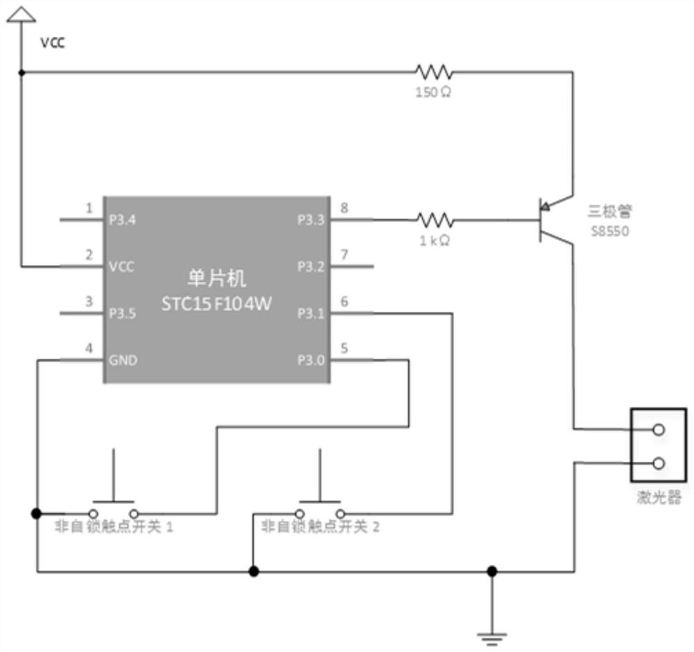
[0057] In terms of function, it includes two parts: the measurement channel and the control channel; the measurement channel adopts open technology, such as Figure 6 As shown, the basic measurement function of the pulse electric field is realized; the invention realizes the self-calibration function of the sensitivity of the pulse electric field detector through the control channel.

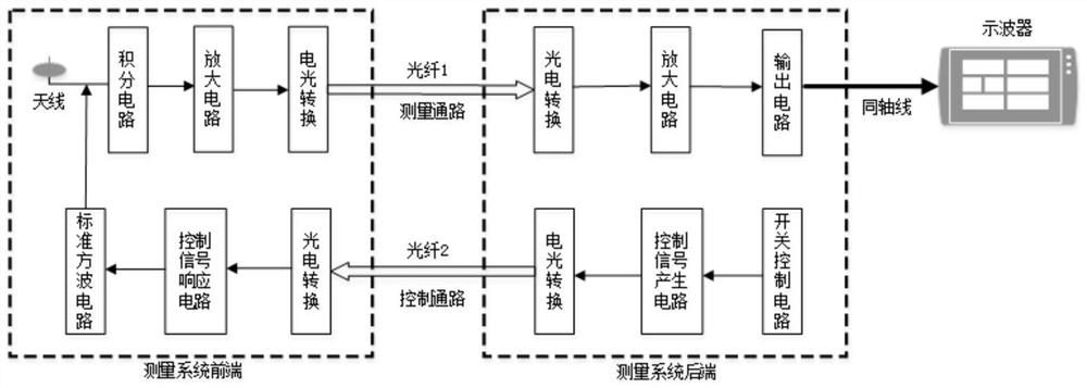
[0058] In terms of composition, the pulsed electric field detector is still divided into two parts, the front end and the back end, such as figure 1 shown. The front end and the back end of the detector need to be connected by two optical fibers, the optical fiber 1 is used for the measurement channel, and the optical fiber 2 is used for the control channel.

[0059] After adding the self-calibration function to the pulse electric field detector, the connection relationship o...


PUM


Abstract

Pulse electric field detector with self-calibration function of sensitivity coefficient and its use method, including two parts: the front end of the detector and the back end of the detector; the front end of the detector includes the front end antenna, integrating circuit, amplifier circuit, electro-optic conversion circuit, electro-optic conversion circuit, control signal Response circuit and standard square wave generation circuit; the back end of the detector includes photoelectric conversion circuit, amplifier circuit, output circuit, photoelectric conversion circuit, switch control circuit, control signal generation circuit and electro-optic conversion circuit; the detector is placed in a standard pulse field environment , get its sensitivity coefficient S 0 , in the laboratory sensitivity coefficient stage, record the output amplitude U of the standard square wave transmitted from the front end to the back end through electro-optic-photoelectric conversion 0 ;In actual use, read the standard square wave output amplitude U in the current state 1 ;Sensitivity coefficient S of the system under the current test state 1 =S 0 ×(U 0 ÷ U 1 ), the present invention improves the accuracy of pulse electric field measurement.

Description

technical field [0001] The invention relates to the technical field of pulse electric field measurement, in particular to a pulse electric field detector with a sensitivity coefficient self-calibration function and a use method. Background technique [0002] As a transient electromagnetic phenomenon, electromagnetic pulse has the characteristics of high instantaneous energy, wide frequency spectrum, and high field strength. Electromagnetic pulses can cause interference or failure to electronic equipment through holes, cables and other channels, so the measurement of pulsed electric field signals is particularly important. [0003] (1) Classification of pulsed electric field detectors: [0004] Pulse electric field measurement detectors can be divided into passive detectors and active detectors. [0005] The pulsed electric field passive detector does not need a built-in power supply. The antenna structure includes a monopole cylindrical antenna, an asymptotic conical anten...

Claims


Application Information

Patent Timeline
Patent Type & Authority Patents(China)
IPC IPC(8): G01R29/08
CPCG01R29/08
Inventor 卢小丽马良
Owner 西安核创能源科技有限公司
Learn More