
A multifunctional food processor

A food processing machine and multi-functional technology, applied in the field of food processing, can solve the problems that a single cup body cannot make hot drinks and vacuum at the same time, is not intelligent enough, and is prone to errors, etc., and achieves the effect of reducing foam, facilitating freshness preservation, and avoiding ineffective work.

Active Publication Date: 2021-08-06
JOYOUNG CO LTD
View PDF6 Cites 0 Cited by
  • Summary
  • Abstract
  • Description
  • Claims
  • Application Information

AI Technical Summary

Problems solved by technology

Users will use different cup bodies for different needs, and each cup body completes its own program work independently. The user needs to manually press the relevant function key to facilitate each cup body to complete its own working program. Therefore It is more complicated, not intelligent enough, and prone to errors, and the existing single cup body cannot be used for hot drinks and vacuum at the same time (vacuum needs to be sealed and pumped, and hot drinks need ventilation and heat dissipation)

Method used


Image

  • A multifunctional food processor
  • A multifunctional food processor
  • A multifunctional food processor

Examples


Embodiment 1

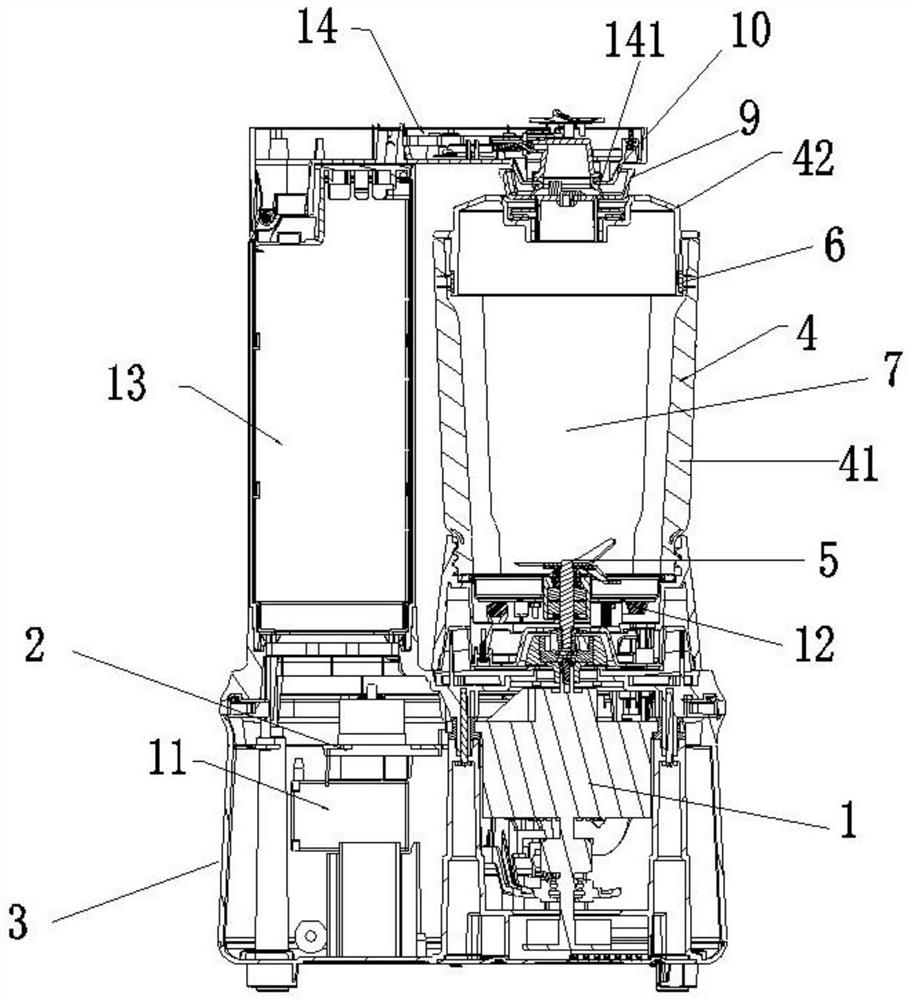
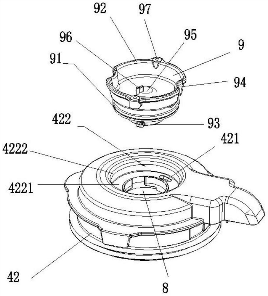
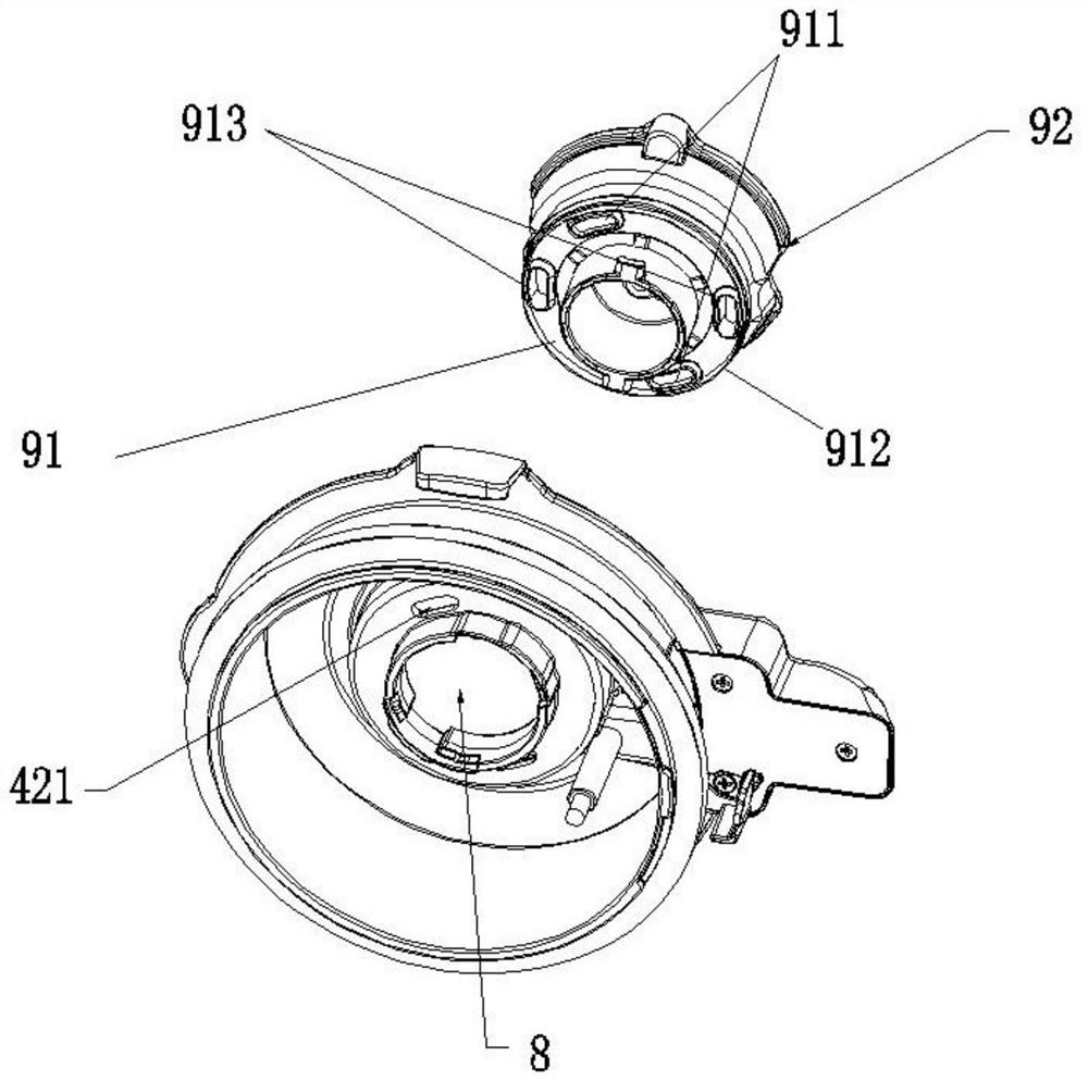
[0034] Such as Figure 1-3As mentioned above, the present invention provides a multifunctional food processor, which includes a base 3 with a motor 1 and a control board 2, a stirring cup 4 connected to the base 3, and a crushing knife 5 arranged in the stirring cup 4. The stirring cup 4 includes a cup body 41 and a cup cover 42. The cup cover 42 is sealed on the upper end of the cup body. The inner wall of the port is fitted together to realize the sealing between the cup cover 42 and the cup body. The cup cover 42 and the cup body form a crushing space 7, and the motor 1 drives the crushing knife 5 to rotate, wherein the cup cover 42 There is a feeding port 8 on the top, and the feeding port 8 is provided with a relatively rotatable feeding cover 9. When the feeding cover 9 rotates to the first position, the crushing space 7 communicates with the outside world, and the feeding cover 9 rotates to the second position. position, the crushing space 7 is separated from the outsi...

Embodiment 2

[0053] Such as Figure 8 As shown, the difference between this embodiment and Embodiment 1 is that the air outlet 421 is arranged on the side wall of the annular sinker 422, the air vent 911 is arranged on the side wall of the feeding cover 9, and the air outlet 421 and the air outlet 911 The positions are equivalent, and a sealing ring is provided between the feeding cover 9 and the annular sinking platform 422 below the vent hole 911 to realize surface-to-face sealing, ensuring that gas can only be discharged to the outside world after passing through the vent hole 421 and the vent hole 911. The advantage of this arrangement is that the sealing and opening effect of the first embodiment can also be achieved by changing the upper and lower penetrations in the first embodiment to the left and right penetrations.

Embodiment 3

[0055] Such as Figure 9 As shown, the difference between this embodiment and Embodiment 1 is that: the air outlet 421 is provided on the top of the cup cover 42, and is arranged vertically through, and the gripping portion 92 of the feeding cover 9 includes an extension plate 15, which is arranged There is a gap on the air outlet 421, and the lower surface of the extension plate is provided with a downwardly protruding sealing column 16. The sealing column is made of silica gel. When it is rotated to the first position, the air outlet 421 is directly connected to the atmosphere. When rotating to the second position, the sealing column just seals the air outlet 421 to achieve sealing. This setting can also replace the sealing method in the first embodiment.


PUM


Abstract

The invention discloses a multifunctional food processing machine, which comprises a machine base with a motor, a control panel, a stirring cup connected with the machine base, and a crushing knife arranged in the stirring cup. The stirring cup includes a cup body and a cup cover , the cup cover is sealed and arranged on the upper end of the cup body, the cup cover and the cup body are enclosed to form a crushing space, and the motor drives the crushing knife to rotate, wherein, the cup cover is provided with a feeding port, and the feeding The mouth is provided with a feeding cover that can rotate relative to the cup cover. When the feeding cover is rotated to the first position, the crushing space is connected with the outside world. When the feeding cover is rotated to the second position, the crushing space is separated from the outside world. The food processing machine also includes an identification device connected to the control board. The identification device recognizes that the feeding cover is in the first position or the second position, and feeds back the identified signal to the control board. The rotation angle of the feeding cover is α, where 5° ≤α≤180° to achieve multi-function.

Description

technical field [0001] The invention relates to the field of food processing, in particular to a multifunctional food processing machine. Background technique [0002] Existing food processing machines include a plurality of cups, such as hot cups, which have a heating device for making hot drinks; cold cups, which do not have a heating device and are used for direct crushing; also have vacuum cups, which vacuum The cup is vacuumed. Users will use different cup bodies for different needs, and each cup body completes its own program work independently. The user needs to manually press the relevant function key to facilitate each cup body to complete its own working program. Therefore It is more complicated, not intelligent enough, and prone to errors, and the existing single cup body cannot do hot drinks and vacuum at the same time (vacuum needs to be sealed and pumped, and hot drinks need ventilation and heat dissipation). Contents of the invention [0003] The object of...

Claims


Application Information

Patent Timeline
Patent Type & Authority Patents(China)
IPC IPC(8): A47J44/02
CPCA47J44/02
Inventor 王旭宁廖朝正郭先炳
Owner JOYOUNG CO LTD
Learn More