A device for filtering fiber suspensions

A technology for filtering fibers and suspensions. It is used in devices for filtering fiber suspensions and in the field of suspensions that are difficult to dehydrate. It can solve problems such as increased distance, adhesion, and expensive structures, and achieve less operational interference, service requirements, and production capacity. High and good effect of process operation

Inactive Publication Date: 2019-01-04
VALMET TECH OY
View PDF9 Cites 1 Cited by
  • Summary
  • Abstract
  • Description
  • Claims
  • Application Information

AI Technical Summary

Problems solved by technology

In order to avoid scraping and thus thickening in the filter cylinder, the distance between the chute and the rotating disk must be made larger, which also leads to this solution making the filter plant less economical
[0007] The second main type of disc filter has the disadvantage that its construction is relatively expensive in the case where the internal longitudinal screw conveyor is placed inside the rotor part of the filter
There is also a big disadvantage that a failure of the conveyor will render the entire filter unusable
[0008] The third main type of disc filter has the disadvantage that the filtrate is diluted by water jets from a vibrating washing device of the filter surface, which leads to dilution of the filtrate without any control and cannot be designed in an optimal way Devices for removing leachate to avoid the leached pulp sticking to the edges of these devices
Vibrating wash nozzles do not yet provide a completely good washing of the entire filter surface depending on the filter sector speed relative to the vibrating nozzle speed and when the filtered pulp can fall between the wash nozzles and the filter surface of the disc

Method used


Image

  • A device for filtering fiber suspensions
  • A device for filtering fiber suspensions
  • A device for filtering fiber suspensions

Examples


Embodiment Construction

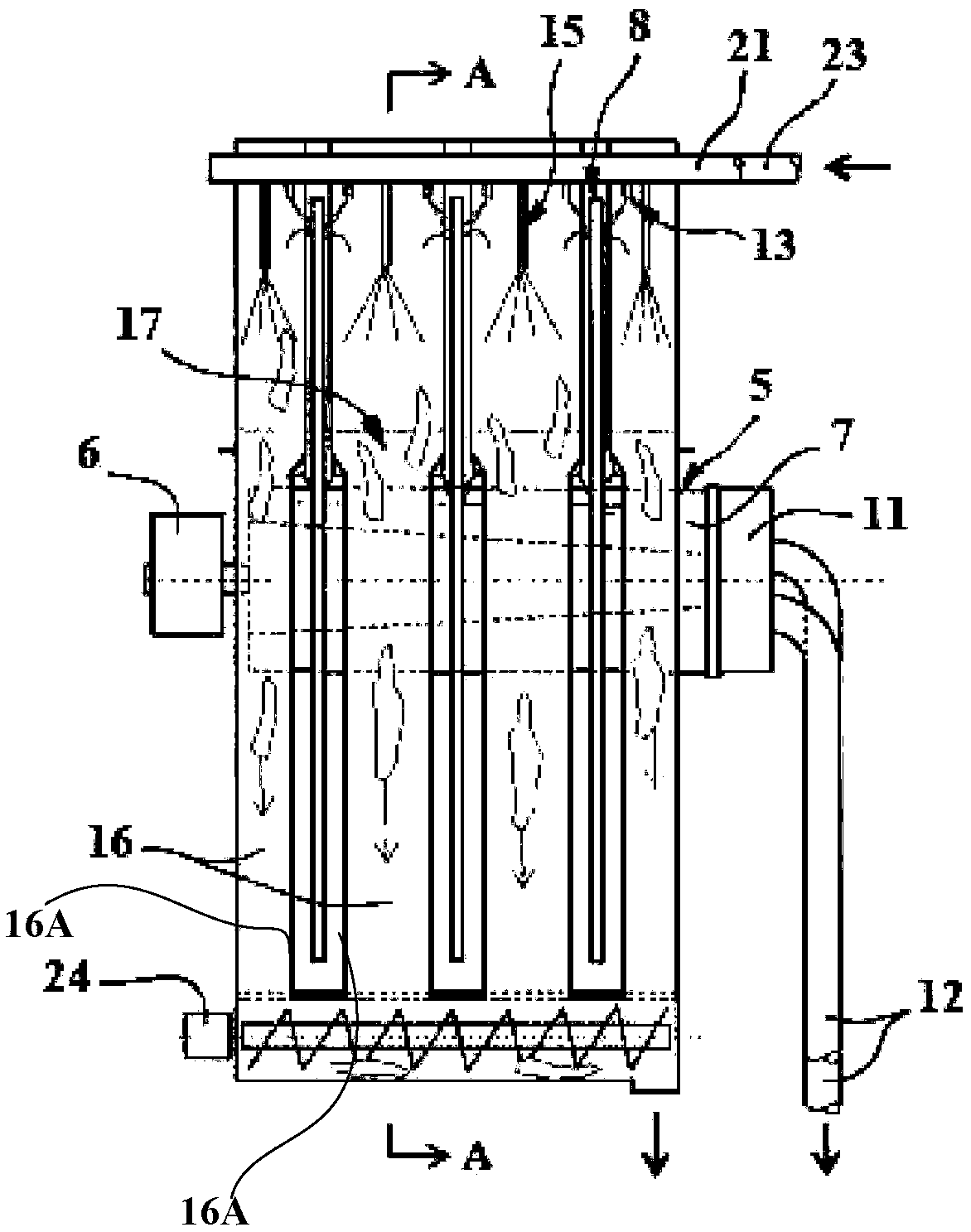
[0040] In the following, a filter device according to the invention which is suitable for dewatering and thickening a fiber suspension which is relatively easy to dewater will be described, but which is also advantageously used for a suspension which is difficult to dewater.

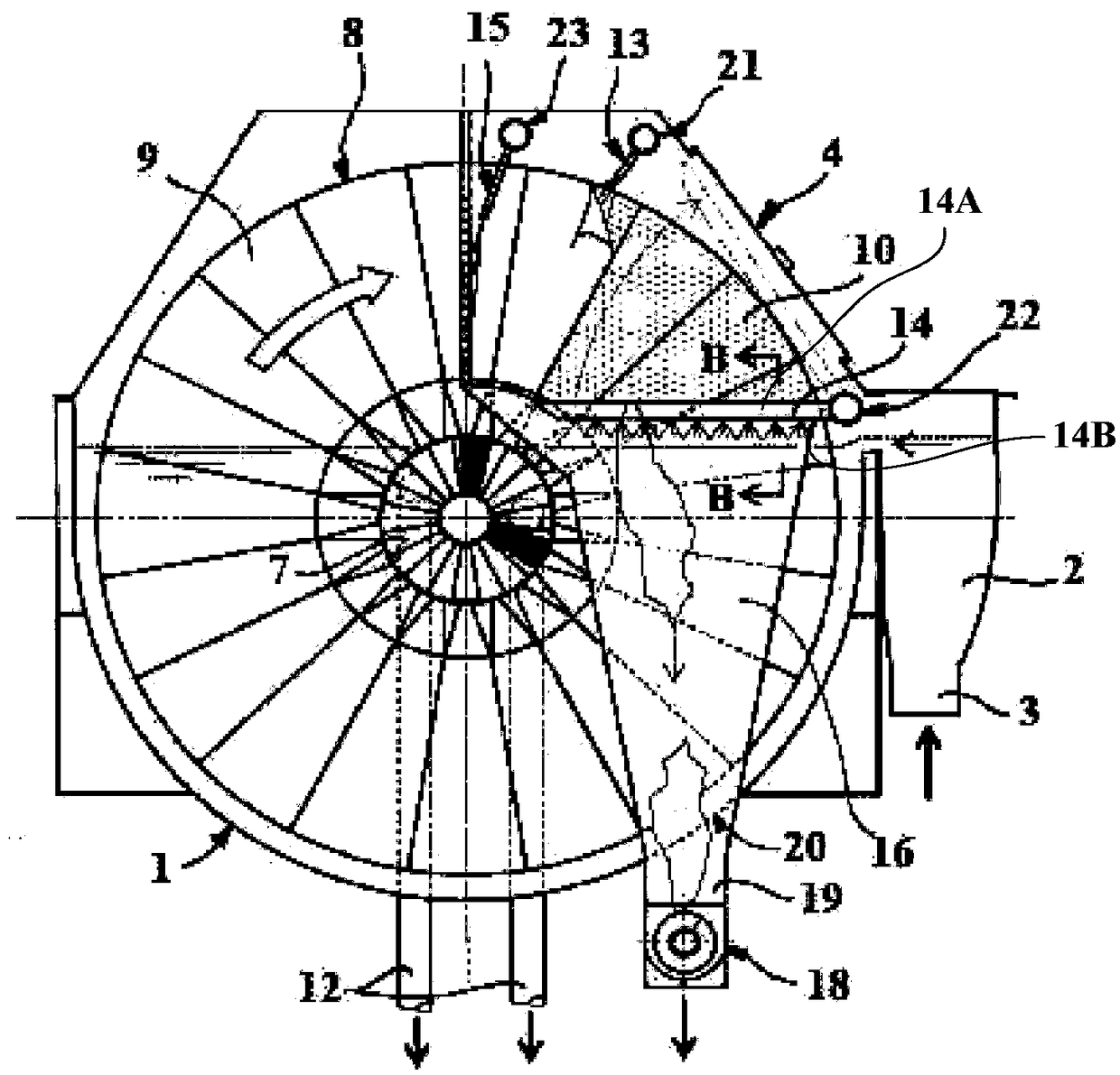
[0041]The filtering device consists of a U-shaped cylinder with a triangular and supporting structure, marked 1, and an inlet 2 for the fiber suspension. The inlet 2 is provided along one side of the cylinder 1 . Inlet tube marked 3 leads to inlet 2. The upper part of the cylinder is sealed with one or more hatches 4 which can be opened.

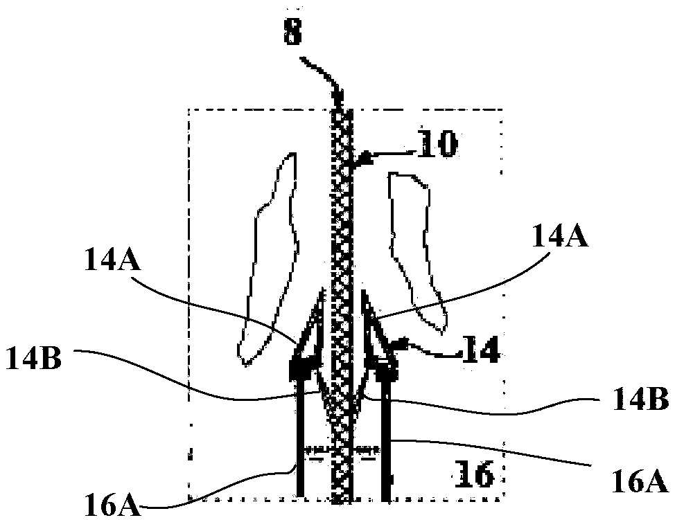
[0042] In the cylinder 1 there is provided an inner rotatable shaft 5 with an actuator 6 , a fluid channel 7 and a plurality of outer disc-shaped filter elements 8 placed across the geometric axis of the inner shaft 5 . The disc-shaped filter element 8 is oriented substantially perpendicular to the axis of rotation of the shaft 5 . Each disc-shaped filter element 8 ...


PUM


Abstract

A device for filtering of fiber suspensions comprises a vat with an inlet for the suspension. In the vat has been arranged a rotatable axis with peripheral channels and at least one disc-like filter element, set at an angle against the rotatable axis. The filter element has a filtering surface and inner flow channels for transporting filtrate, which has passed through the filtering surface, to oneor more channels in the inner rotating axis. The liquid flow in the channels is combined in one end of the rotating axis into at least one barometric downpipe in order to generate the vacuum necessary for filtration. There are means for detaching material deposited on the filtering surface, filtered out of the suspension. Additionally, there are means for guiding out-filtered material down into areceiving chute and for cleaning the filtering surface by means of a number of spray nozzles, and means for flushing the out-filtered material down into at least one receiving chute. Detaching means,washing means and receiving chute are arranged beside the filter element. At the outlet end of the receiving chute and by the bottom part of the vat, there is a transport means with an actuator, arranged to combine and transport away the out-filtered material.

Description

technical field [0001] The object of the present invention is to increase the operational reliability and to improve the filtration results of disc filters for filtering fibrous suspensions, in particular to devices for filtering fibrous suspensions which are characterized by relatively easy dewatering. The invention can also be used for suspensions which are difficult to dewater. Background technique [0002] The term "fiber suspension" refers to liquids and suspensions which contain fibers and other constituents present which are to be filtered out. These fibers are usually regenerated cellulose fibers, but newly produced cellulose fibers can also be problematic. [0003] There are mainly three related types of disc filters in this paper. In the first type of disc filter, a filter for removing detached material is provided between two adjacent discs for filtration. A device shaped like a chute so that its lower part conveys material to a receiving device, the first type ...

Claims


Application Information

Patent Timeline
Patent Type & Authority Applications(China)
IPC IPC(8): B01D33/15B01D33/48
CPCB01D33/15B01D33/48B01D33/463B01D33/466B01D33/60B01D33/21B01D33/50B01D33/70B01D33/76D21C9/06D21C9/18Y02P70/10D21D5/06
Inventor R·奥斯瓦德森K·斯特里德
Owner VALMET TECH OY
Why Eureka
Try Eureka