Shaping device for powder injection molding type clamp part

A technology of powder injection molding and shaping device, which is applied to engine components, other manufacturing equipment/tools, turbines, etc., can solve the problems of complex shaping molds, and achieve the effect of reducing shaping errors

Active Publication Date: 2019-01-04
PINGXIANG HUICHENG PRECISION MACHINERY & ELECTRONICS
View PDF5 Cites 0 Cited by
  • Summary
  • Abstract
  • Description
  • Claims
  • Application Information

AI Technical Summary

Problems solved by technology

[0005] Aiming at the problems existing in the shaping of clip-like parts in the powder injection molding described above, the purpose of the present invention is to provide a solution to the complex problem of shaping molds for similar parts. The positioning of the screw rotation is used to meet the requirements for specific angles or gaps. Plastic clip parts can be reshaped to achieve a powder injection molding clip part reshaping device that can adjust parts with different angles or clearance requirements only by adjusting the screw to change its length. In addition, it is also necessary to consider the part shaping process Pre-deformation, and find a suitable positioning point through multiple experiments, and finally meet the production requirements of the part

Method used


Image

  • Shaping device for powder injection molding type clamp part
  • Shaping device for powder injection molding type clamp part
  • Shaping device for powder injection molding type clamp part

Examples


Embodiment Construction

[0017] In order to make the object, technical solution and effect of the present invention clearer and clearer, the present invention will be described in further detail below with reference to the accompanying drawings and embodiments. It should be understood that the specific embodiments described here are only used to explain the present invention, and are not intended to limit this invention.

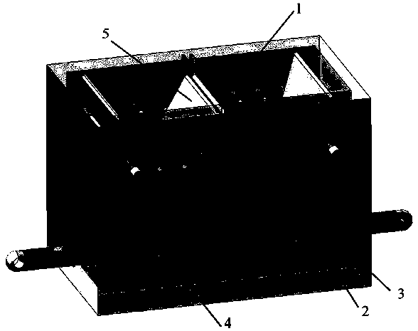
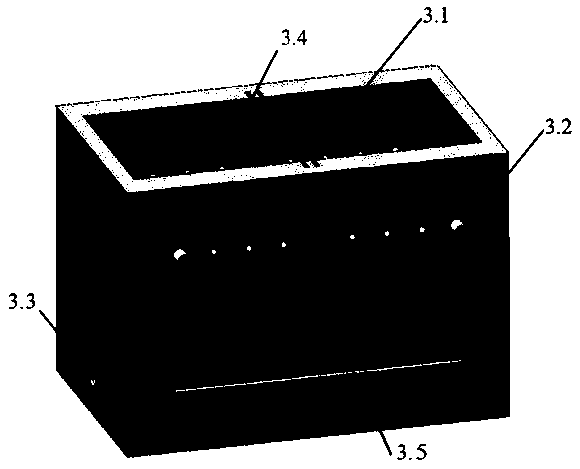
[0018] Such as Figure 2-5 As shown, the shaping device for powder injection molding clip parts includes a frame 3 (in a cuboid hollow structure), a screw positioning device 4, and a baffle 5, and the frame is provided with a baffle and a screw The cavity 1 of the positioning device, the bottom of the frame is provided with a moving chute 2 matching the screw positioning device; the frame 3 includes a frame body 3.1, and the middle part of the inner wall of the long side of the frame body is symmetrically provided with The baffle plate positioning chute 3.4, the long sides of the f...


PUM


Abstract

The invention discloses a shaping device for a powder injection molding type clamp part. The device comprises a rack, a screw positioning device and a baffle plate, wherein the screw positioning device is movably connected to the baffle plate; a storing chamber for storing the baffle plate and the screw positioning device is formed in the rack; a movable chute which fits the screw positioning device is formed in the inner bottom part of the rack; the rack comprises a rack body; baffle plate positioning chutes are symmetrically formed in the middle parts of the inner walls of two side edges ofthe long side of the rack body; a plurality of holes through which pin pass and scale lines are arranged at intervals on two side surfaces of the long side of the rack body; screw inserting holes areformed in two sides of the short side of the rack body; the screw positioning device comprises an inner sliding block, outer sliding blocks and a screw; and the outer sliding blocks are symmetricallyarranged at two sides of the inner sliding block. According to the device, the screw and the scale line are matched to accurately adjust the angle of the baffle plate; the angles or distances of different parts are combined, so that the part shaping effect can be realized without replacing a die under the condition that similar parts are deformed differently.

Description

technical field [0001] The invention relates to the technical field of powder injection molding, in particular to a shaping device for clip parts of powder injection molding. Background technique [0002] Powder injection molding (Powder Injection Molding, PIM for short) is an advanced near-net forming technology that introduces injection molding technology into powder metallurgy. Using PIM technology to manufacture small parts such as "clips" can solve the large-scale problems faced by traditional mechanical manufacturing processes. Part of the problem: directly make integral three-dimensional space structure parts, greatly reduce processing procedures, and material utilization rate can reach 99%. However, the application of the PIM process to the manufacture of three-dimensional structural parts such as "clips" also brings about the problem of "sintering deformation". That is, during the high-temperature sintering process, it is difficult to control the shape and position ...

Claims


Application Information

Patent Timeline
Patent Type & Authority Applications(China)
IPC IPC(8): B22F3/24B22F3/22B22F5/00
CPCB22F3/225B22F3/24B22F5/00
Inventor 黄若高泽肖斌郭文杰
Owner PINGXIANG HUICHENG PRECISION MACHINERY & ELECTRONICS
Why Eureka
Try Eureka