Eureka AIR delivers breakthrough ideas for toughest innovation challenges, trusted by R&D personnel around the world.

a feeding mechanism

A technology of feeding mechanism and material belt, which is applied in thin material handling, transportation and packaging, and winding strips, etc., can solve the problems of poor quality, low work efficiency, easy flattening and crushing of copper shells, etc.

Active Publication Date: 2020-09-25
珠海市欧科锐智能装备有限公司
View PDF4 Cites 0 Cited by
  • Summary
  • Abstract
  • Description
  • Claims
  • Application Information

AI Technical Summary

Problems solved by technology

At present, most of the copper shells are directly stamped on the copper foil strip, and there are generally two types of copper shells on the market: one is an independent copper shell, that is, the copper shell is pre-made from the copper foil strip. Peel off, and then package and sell. Since the copper shell has been stripped from the copper foil strip, it is very convenient for customers to use it in the later stage. It can be used directly, but the production cost is relatively increased, and it is easy to be crushed during transportation. The copper shell is crushed; the other is that the manufacturer simply punches out the copper shell on the copper foil strip, and the copper shell has part of the structure connected to the copper foil strip. This method is compared with the previous independent copper foil strip. Shell, the processing method is simple. The manufacturer only needs to stamp the copper shell without punching it, and then roll it together with the material tape into a bundle, which is convenient for later storage and transportation. However, since the copper shell is not removed from the material Stripping on the strip requires stripping the copper shell from the strip before assembling, so the production cost of the assembled transformer manufacturer increases
[0003] For the latter type of copper shell, most manufacturers currently use manual or other stripping equipment to peel the copper shell from the strip before assembling the terminals. Manual stripping is used, which results in low work efficiency and poor overall quality; Peeling with stripping equipment usually works together with the feeding equipment. The feeding mechanism feeds the coiled strip, and then the stripping equipment strips the copper shell from the strip. The work efficiency is high, but the production cost is high, and due to the copper shell It is directly stamped on the material strip, so it needs to be peeled off from the material strip. First, the positional relationship between the copper shell and the material strip needs to be adjusted to expose the connection and place between the copper shell and the material strip, and the peeling equipment Only then can the connection between the two be printed, which is convenient for later twisting and peeling off the copper shell from the strip
At present, this process is mostly manually adjusted or the copper shell is peeled off without adjustment. If the feeding mechanism is not adjusted directly, the next step of peeling the copper shell will be carried out, which will affect the quality of the copper shell stripped out later. Poor, low yield, directly affects the quality of later transformer assembly

Method used


Image

  • a feeding mechanism
  • a feeding mechanism
  • a feeding mechanism

Examples


Embodiment Construction

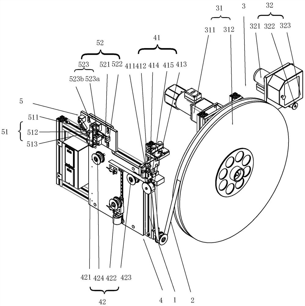
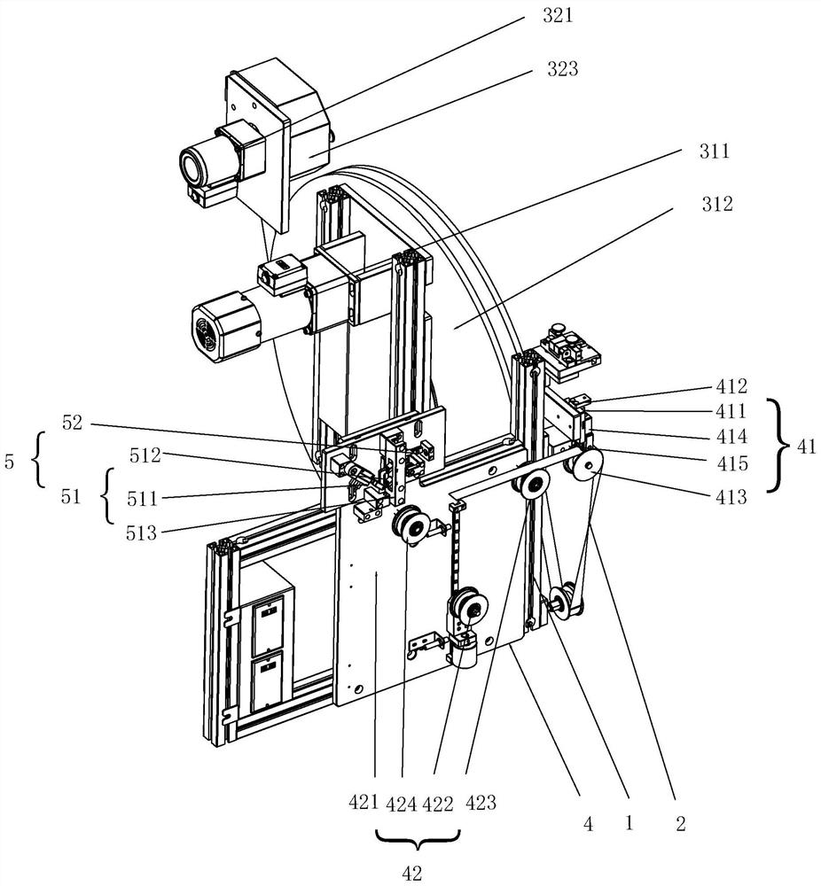
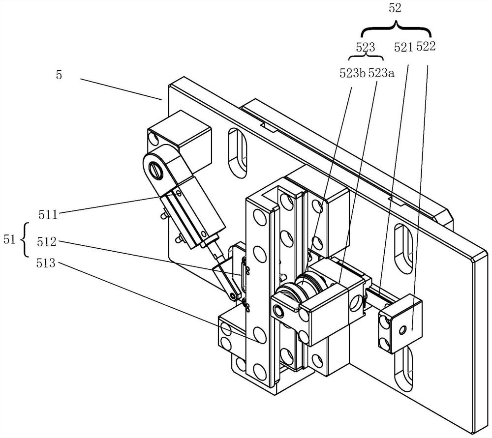
[0026] see Figure 1 to Figure 7 , a kind of feeding mechanism of the present invention, comprises frame 1, and frame 1 is provided with the discharge group 3 that is used for feeding material belt 2, the adjustment group 4 that is used to adjust the tightness of material belt 2 and is used for adjusting material belt 2 The shaping group 5 at the position of the upper copper shell, the material belt 2 sent by the discharging group 3 passes through the adjusting group 4 and is connected with the shaping group 5, and the shaping group 5 is provided with a toggle head 51 and a positioning member 52, as a material belt 2. When the toggle head 51 travels between the positioning members 52, the toggle head 51 can be reciprocally inserted into the copper shell and cooperate with the positioning member 52 to pry and adjust the angle of the copper shell on the strip 2. which see Figure 7 It can be seen that in this application, the buckle of the copper shell is adhered to the materia...


PUM


Abstract

The invention discloses a feeding mechanism, which includes a rack, a discharging group, an adjusting group and a shaping group for adjusting the position of a copper shell on a material belt. The material belt sent out by the discharging group is connected with the shaping group through the adjusting group, the shaping group is provided with a toggle head and a positioning component, and when thematerial belt passes between the toggle head and the positioning component, the toggle head can be inserted into the copper shell in a reciprocating mode and matched with the positioning component tolever and regulate the angle of the copper shell on the material belt; and the toggle head on the shaping group is used for being matched with the positioning component, the copper shell passing through the material belt between the toggle head and the positioning component can be subjected to position adjustment through mutual cooperation of the toggle head and the positioning component, the toggle head is used for being matched with the positioning component to lever the angle of the copper shell, the joint between the copper shell and the material belt is exposed, a copper shell body doesnot resist the joint, the shaping effect is achieved, and the copper shell is conveniently stripped through stripping equipment in the later stage. According to the feeding mechanism, the position ofthe copper shell can be effectively adjusted, the copper shell is conveniently stripped from the material belt in the later stage, the structure is simple, and operation is convenient.

Description

technical field [0001] The invention relates to the technical field of transformer production equipment, in particular to a feeding mechanism. Background technique [0002] At present, when the transformer is assembled in the later stage, the coil is wound on the skeleton first, then the magnetic core is installed to form the terminal, and finally the copper shell and the terminal are assembled. At present, most of the copper shells are directly stamped on the copper foil strip, and there are generally two types of copper shells on the market: one is an independent copper shell, that is, the copper shell is pre-made from the copper foil strip. Peel off, and then package and sell. Since the copper shell has been stripped from the copper foil strip, it is very convenient for customers to use it in the later stage. It can be used directly, but the production cost is relatively increased, and it is easy to be crushed during transportation. The copper shell is crushed; the other...

Claims


Application Information

Patent Timeline
Patent Type & Authority Patents(China)
IPC IPC(8): B65H16/10B65H23/26
CPCB65H16/103B65H23/26
Inventor 吴兴基
Owner 珠海市欧科锐智能装备有限公司
Why Eureka
Eureka Blog
Learn More