
Cemented carbide pipe fitting

A technology of hard alloy and pipe fittings, which is applied in the direction of metal processing machinery parts, pipe cutting devices, metal processing equipment, etc., can solve the problems of cumbersome operation steps, human hazards, waste of manpower, etc., to prevent dust from flying, prevent safety hazards, The effect of simple and convenient clamping steps

Inactive Publication Date: 2019-01-04
广州大正机械科技开发有限公司
View PDF0 Cites 3 Cited by
  • Summary
  • Abstract
  • Description
  • Claims
  • Application Information

AI Technical Summary

Problems solved by technology

[0002] When processing cemented carbide pipe fittings, it needs to be cut. At present, the cutting work is usually carried out by manual hand-held cutting machines. When using it, it is easy to generate a lot of dust, which is easy to cause harm to the human body and the environment. Moreover, during the cutting process , it is necessary to clamp the cemented carbide pipe fittings. At present, the clamping equipment is usually used alone for clamping. The operation steps are cumbersome and a lot of manpower is wasted. Therefore, it needs to be improved

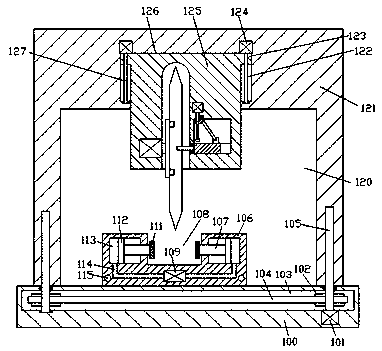
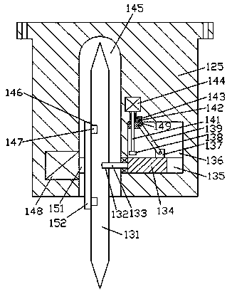
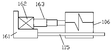
Method used


Image

  • Cemented carbide pipe fitting
  • Cemented carbide pipe fitting
  • Cemented carbide pipe fitting

Examples


Embodiment Construction

[0013] Combine below Figure 1-3 The present invention will be described in detail.

[0014] refer to Figure 1-3 , a cemented carbide pipe fitting according to an embodiment of the present invention, comprising a base plate 100 and a cover body 121 installed on the upper side of the base plate 100, the bottom end surface of the cover body 121 is provided with an accommodating cavity 120, and the accommodating cavity 120, the top wall is provided with a first chute 126, and a processing seat 125 is installed in the first chute 126 for sliding fit. A recessed groove 145 is provided, and a cutting blade 131 is rotated in the recessed groove 145, and a first plug-in groove 146 is arranged symmetrically up and down in the left end surface of the cutting blade 131, and in the center of the right end surface of the cutting blade 131 There is a second plug-in groove 132, the first electric roller 148 is fixed in the inner wall on the left side of the concave groove 145, and the out...


PUM


Abstract

The invention discloses a cemented carbide pipe fitting. The cemented carbide pipe fitting comprises a base plate and a cover body mounted on the base plate. The end face of the bottom of the cover plate is internally provided with a containing cavity. The top wall of the containing cavity is internally provided with a first sliding groove. A machining seat is mounted in the first sliding groove in a sliding fit mode. The left and right sides of the machining seat are symmetrically provided with lifting mechanisms. The end face of the bottom of the machining seat is internally provided with asunken groove. A cutting blade is rotatably arranged in the sunken groove. The left end face of the cutting blade is internally provided with first insertion-connection grooves in longitudinal symmetry. A second insertion-connection groove is formed in the center of the right end face of the cutting blade. A first electric roller is fixedly arranged in the inner wall of the left side of the sunkengroove. A clamping plate is fixedly arranged on an output shaft of the right side end of the first electric roller. The right end face of the clamping plate is fixedly provided with insertion-connection plates connected with the first insertion-connection grooves in longitudinal symmetry, and the insertion-connection plates are connected with the first insertion-connection grooves in an insertion-connection fit mode.

Description

technical field [0001] The invention relates to the technical field of processing cemented carbide pipe fittings, in particular to a cemented carbide pipe fitting. Background technique [0002] When processing tungsten carbide pipe fittings, it needs to be cut. At present, the cutting work is usually carried out by manual hand-held cutting machines. When using it, it is easy to generate a lot of dust, which is easy to cause harm to the human body and the environment. Moreover, during the cutting process , it is necessary to clamp the cemented carbide pipe fittings. At present, the clamping equipment is usually used alone for clamping. The operation steps are cumbersome and a lot of manpower is wasted. Therefore, it needs to be improved. Contents of the invention [0003] The object of the present invention is to provide a cemented carbide pipe fitting for overcoming the above-mentioned defects in the prior art. [0004] A cemented carbide pipe fitting according to the pre...

Claims


Application Information

Patent Timeline
IPC IPC(8): B23D21/00B23D33/00B23D33/02B23D35/00B23Q11/08
CPCB23D21/00B23D33/00B23D33/02B23D35/004B23Q11/08
Inventor 聂值清
Owner 广州大正机械科技开发有限公司
Learn More