Lining sleeve milling groove machining tooling

A technology for milling grooves and bushings, which is applied in metal processing equipment, metal processing mechanical parts, positioning devices, etc., can solve the problems of troublesome positioning, time-consuming, and large errors of cylindrical structures, and achieves low power, efficiency, and efficiency. Improved accuracy and reduced friction

Active Publication Date: 2019-01-04
金成技术股份有限公司
View PDF7 Cites 2 Cited by
  • Summary
  • Abstract
  • Description
  • Claims
  • Application Information

AI Technical Summary

Problems solved by technology

Sometimes it is necessary to process milling grooves on the outside of the bushing, especially to process multiple grooves on one bushing. Because of its cylindrical structure, it is troublesome to locate. Now when the bushing is milling grooves, it is first on the outer wall of the bushing. Make the upper and lower marks, and then clamp the bushing directly on the fixture of the milling machine through measurement or experience; this is inaccurate, time-consuming and inefficient; especially when machining symmetrical grooves, by marking in advance and clamping, very large error

Method used


Image

  • Lining sleeve milling groove machining tooling
  • Lining sleeve milling groove machining tooling
  • Lining sleeve milling groove machining tooling

Examples


Embodiment 1

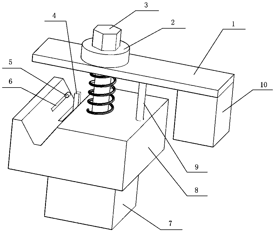
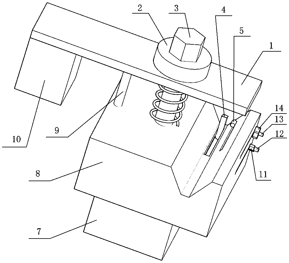
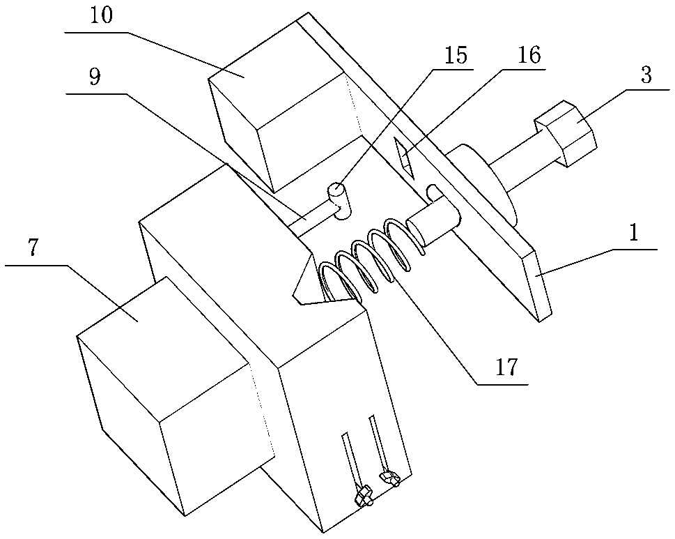
[0026] In the bush milling tooling described above, a spring 17 is sleeved on the part of the pressing bolt 3 between the pressing plate 1 and the clamping block 8; The lower part is provided with a rotating shaft chamber 16 adapted to the rotating shaft 15 , and the rotating shaft 15 is hinged to the side walls at both ends of the rotating shaft chamber 16 .

Embodiment 2

[0028] In the bush milling tooling described above, a counterweight 10 is provided at the rear of the pressure plate 1; a rotating shaft 15 is provided at the upper end of the support column 9, and a rotating shaft cavity 16 adapted to the rotating shaft 15 is provided at the lower part of the pressing plate 1. The rotating shaft 15 is connected to the rotating shaft chamber 16 in a detachable and rotatable manner.

Embodiment 3

[0030] In the bush milling tooling described above, a counterweight 10 is provided at the rear of the pressure plate 1, and a spring 17 is sleeved on the part of the compression bolt 3 between the pressure plate 1 and the clamping block 8; the upper end of the support column 9 A rotating shaft 15 is provided, and a rotating shaft chamber 16 adapted to the rotating shaft 15 is provided at the lower part of the pressure plate 1 , and the rotating shaft 15 is connected to the rotating shaft chamber 16 in a rotatable manner.

[0031] The working principle is: because the milling cutter is vertically above, the uppermost part of the first stop disc 21 is the starting point, and the vertical hole at the bottom of the first stop disc 21 opposite to the starting point is the end hole, and the central angle between the connecting hole and the starting point is For the angle suitable for positioning, that is, the central angle between the connection hole and the starting point is equal t...


PUM


Abstract

The invention provides a lining sleeve milling groove machining tooling. The lining sleeve milling groove machining tooling comprises a pressing plate, a compressing bolt, a clamping block and a supporting column, wherein the clamping block is a cuboid metal block with one side of the upper portion being provided with a V groove, the bottom of the V groove is provided with a first sliding rail with the cross section being in an L shape, the first sliding rail communicates with the bottom of the V groove and the side wall of the clamping block, the side wall of the V groove is further providedwith a second sliding rail communicating with the side wall of the clamping block, the first sliding rail and the second sliding rail are internally provided with slideable positioning structures, theupper portion of the clamping block is provided with the pressing plate, the pressing plate is connected with the clamping block through the supporting column, the lower end of the supporting columnis connected with the upper portion of the clamping block, the upper end of the supporting column is connected with the pressing plate in a rotatable manner, the part, between the V groove and the supporting column, of the clamping block is provided with a thread blind hole, the position, directly opposite to the thread blind hole in the vertical direction, in the pressing plate is provided with athrough hole, and the through hole is internally provided with the compressing bolt in a penetrating manner. By means of the lining sleeve milling groove machining tooling, a lining sleeve can be rapidly and accurately positioned, and especially when multiple grooves are machined around the circumference of the lining sleeve, compared with existing mark measurement method clamping and experiencemethod clamping, the efficiency and accuracy are improved a lot.

Description

Technical field: [0001] The invention relates to the technical field of bush processing tooling, in particular to a bushing groove milling tooling. Background technique: [0002] The bushing is an accessory used outside the mechanical parts to achieve sealing, wear protection, etc., and refers to the ring sleeve that acts as a gasket. Sometimes it is necessary to process milling grooves on the outside of the bushing, especially to process multiple grooves on one bushing, because of its cylindrical structure, it is more troublesome to locate. Now when the bushing is milling grooves, it is first on the outer wall of the bushing. Make marks on the top and bottom, and then clamp the bushing directly on the fixture of the milling machine through measurement or experience; this is inaccurate, time-consuming and inefficient; especially when machining symmetrical grooves, by marking and clamping in advance, The error is very large. Invention content: [0003] In order to solve t...

Claims


Application Information

Patent Timeline
Patent Type & Authority Applications(China)
IPC IPC(8): B23Q3/06
CPCB23Q3/06Y02P70/10
Inventor 曹务新李月民郭文文
Owner 金成技术股份有限公司
Why Eureka
Try Eureka