Cooling device for films

A cooling device and film technology, applied in the field of film cooling, can solve the problems of high labor intensity and inconvenient operation, and achieve the effect of avoiding high labor intensity and simple and convenient operation.

Active Publication Date: 2019-01-04
MESNAC
View PDF6 Cites 1 Cited by
  • Summary
  • Abstract
  • Description
  • Claims
  • Application Information

AI Technical Summary

Problems solved by technology

[0004] The object of the present invention is to provide a film cooling device to solve the problems of inconvenient operation and high labor intensity for installing the film to the cooling drum when the cooling device is in use

Method used


Image

  • Cooling device for films
  • Cooling device for films
  • Cooling device for films

Examples


Embodiment Construction

[0027] The core of the present invention is to provide a cooling device for the film, so as to solve the problems of inconvenient operation and high labor intensity of installing the film to the cooling drum when the cooling device is used.

[0028] In order to make those skilled in the art better understand the technical solutions provided by the present invention, the present invention will be further described in detail below with reference to the accompanying drawings and specific embodiments.

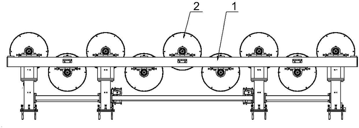
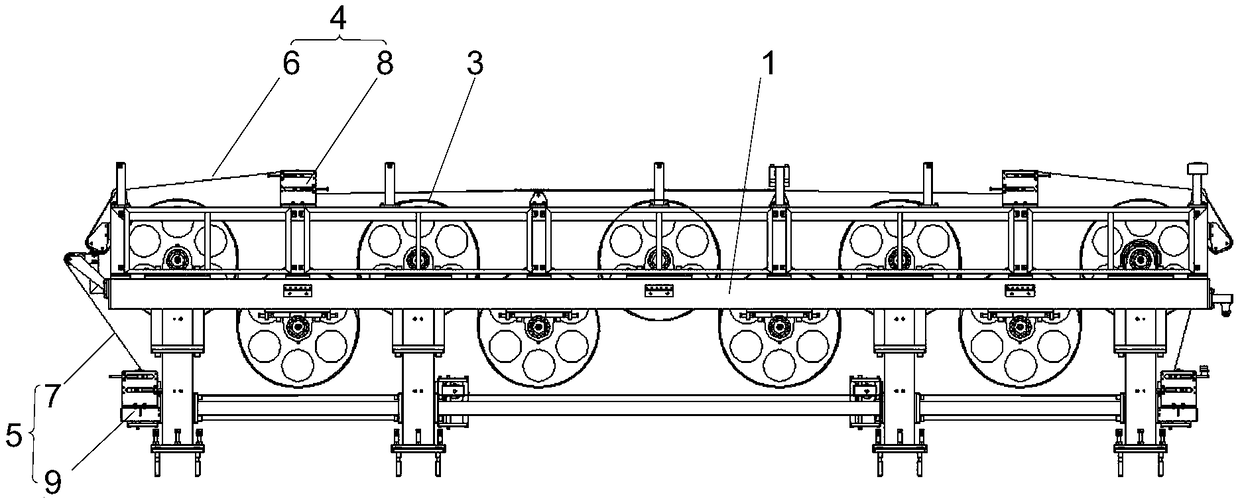
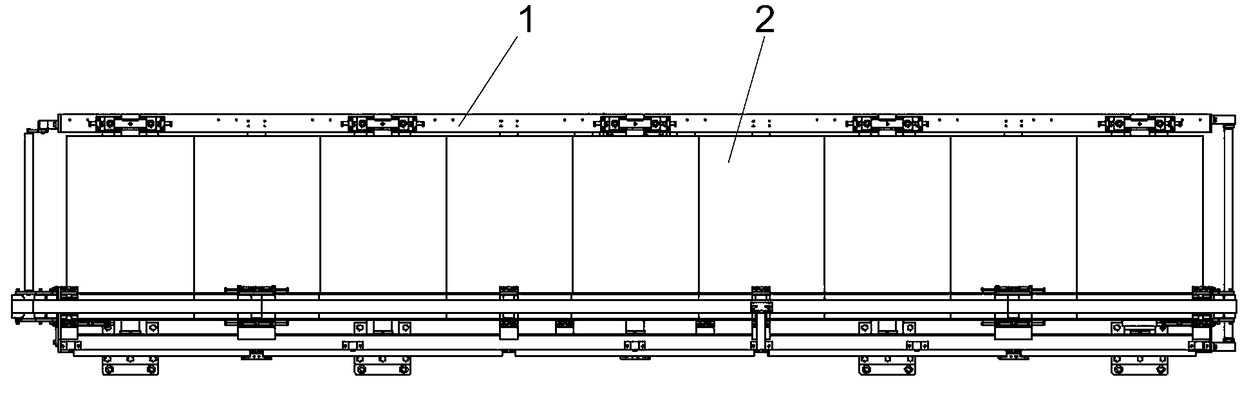
[0029] like Figure 2-Figure 7 As shown, an embodiment of the present invention provides a cooling device for a film, comprising a rack 1 and a cooling drum 2 arranged on the rack 1 in an alternate manner from top to bottom, and the cooling device further includes a feed drum arranged on the rack 1 3. The upper guide assembly 4 located above the frame 1, the lower guide assembly 5 located below the frame 1, the upper guide belt 6 sleeved on the upper guide assembly 4 and the guide ...


PUM


Abstract

The invention discloses a cooling device for films. The cooling device comprises a machine frame and cooling drums arranged on the machine frame in a vertically alternate manner; the cooling device further comprises a feeding drum arranged on the machine frame, an upper guiding component arranged at the upper part of the machine frame, a lower guiding component arranged at the lower part of the machine frame, an upper feeding belt sleeved on the upper guiding component and the feeding drums, and a lower feeding belt sleeved on the lower guiding component and the feeding belt; the feeding drumsand the cooling drum are arranged coaxially, and the diameters of the feeding drum and the diameter of the cooling drum are the same; and the upper guiding belt and the lower guiding belt, which workalong the same track, pass through the gaps of two adjacent feeding drums one by one from one end of the machine frame. The cooling device has the advantages that a film can be enwound on the coolingdrum which is coaxial with the feeding drum under the function of clamping of the upper feeding belt and the lower feeding belt, the operation is simple and convenient, and the problem that the laborintensity is high when a film is enwound on the cooling drum manually can be avoided.

Description

technical field [0001] The invention relates to the technical field of film cooling, in particular to a film cooling device. Background technique [0002] Generally speaking, the production process of the film generally needs to cool the film, and the current film cooling is mainly carried out by a cooling device, such as figure 1 As shown, the cooling device generally includes a rack 1 and a cooling drum 2 arranged on the rack 1. The cooling drums 2 are arranged in parallel, and are arranged alternately up and down from one end of the rack 1 to the other end of the rack 1 , the cooling drum 2 can rotate around its own axis under the drive of the driving mechanism. When using, it is necessary to manually manually pass the film from the cooling drum 2 at one end of the frame 1 through the gap between the two adjacent cooling drums 2 one by one. Then the cooling drum 2 is driven to rotate to cool the continuously introduced film. In this method, the operation is inconvenient...

Claims


Application Information

Patent Timeline
Patent Type & Authority Applications(China)
IPC IPC(8): B29C35/16
CPCB29C35/16
Inventor 薄夫修戚鹏杨林春宫一青刘朋霞
Owner MESNAC
Why Eureka
Try Eureka