Rotary lining trolley pouring mechanism and method

A lining trolley and rotary technology, which is applied in shaft lining, tunnel lining, earthwork drilling and mining, etc., can solve the problems of concrete segregation, inability to change flexibly, and poor fluidity of secondary lining concrete, and achieve compact structure, high precision, and load-carrying powerful effect

Pending Publication Date: 2022-01-21
CHINA RAILWAY FIRST GRP CO LTD +1
View PDF0 Cites 0 Cited by
  • Summary
  • Abstract
  • Description
  • Claims
  • Application Information

AI Technical Summary

Problems solved by technology

However, due to the limited structural space of the lining trolley, and the unreasonable angle and position of the chute and the collusion, the fluidity of the secondary lining concrete is poor; at the same time, due to improper human operation during the construction process, ash will be injected on both sides at the same time. This further leads to the problem of concrete segregation; the chute and the collusion mechanism can only be installed on the fixed pouring window of the trolley, and cannot be flexibly changed, resulting in the failure to realize layered and window-by-window pouring in the true sense. Therefore, the above problems seriously affect the secondary lining concrete. Construction Quality

Method used


Image

  • Rotary lining trolley pouring mechanism and method
  • Rotary lining trolley pouring mechanism and method
  • Rotary lining trolley pouring mechanism and method

Examples


Embodiment Construction

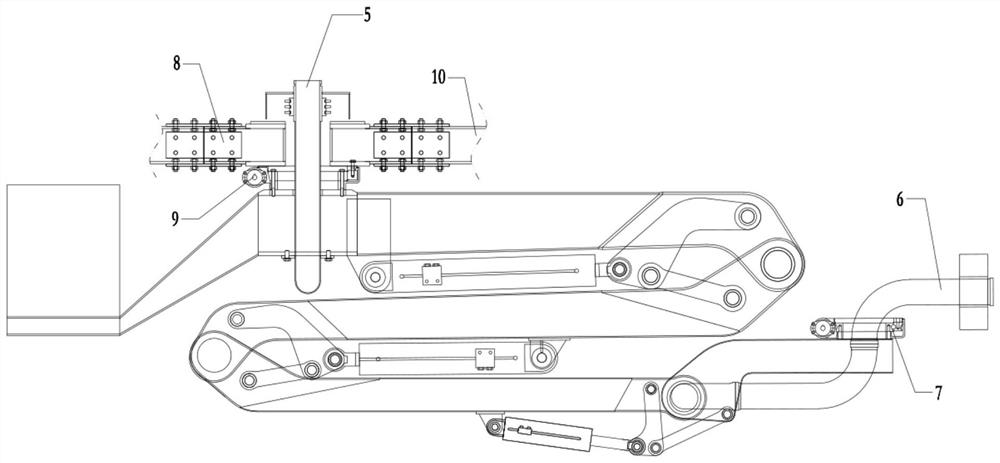
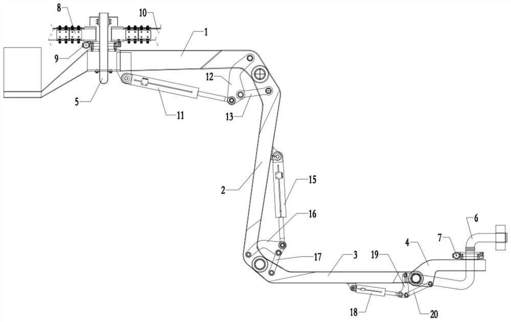
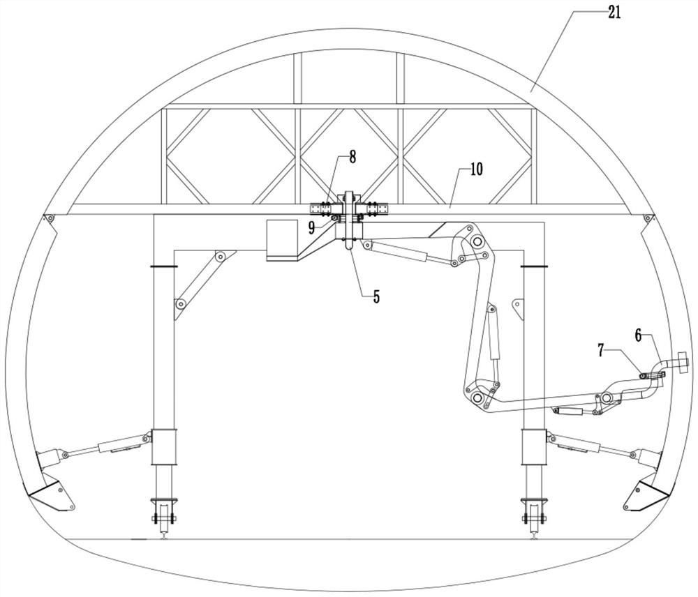
[0056] Such as Figure 1 to Figure 6 The pouring mechanism of a rotary lining trolley shown includes a grouting unit and a rotating support installed on the lining trolley 21 for driving the boom to rotate;

[0057] The boom includes a first joint arm 1, a second joint arm 2, a third joint arm 3 and a fourth joint arm 4 which are sequentially hinged, the hinge shafts of the first joint arm 1 and the second joint arm 2, the second joint arm The hinge axes of the second boom 2 and the third boom 3, and the hinge axes of the third boom 3 and the fourth boom 4 are parallel to each other; between the first boom 1 and the second boom 2, a first telescopic Structure; a second telescopic structure is provided between the second section boom 2 and the third section boom 3; a third telescopic structure is provided between the third section boom 3 and the fourth section boom 4;

[0058] The grouting unit includes a pump pipe 5, a grouting pipe 6 and a concrete delivery pump 14, the pump...


PUM


Abstract

The invention discloses a rotary lining trolley pouring mechanism and method. The pouring mechanism comprises a grouting unit and a rotary support installed on a lining trolley and used for driving an arm frame to rotate; the arm frame comprises a first section arm, a second section arm, a third section arm and a fourth section arm which are sequentially connected in a hinged manner; the grouting unit comprises a pump pipe, a grouting pipeline and a concrete conveying pump, the pump pipe is fixed to the arm frame, one end of the pump pipe is connected with a concrete conveying pump, the other end of the pump pipe is rotationally connected with the grouting pipeline, the end of the grouting pipeline is fixed to the end of the fourth section arm, and the outlet end of the grouting pipeline is a grout outlet; and the pouring method comprises the following steps: selecting an initial pouring working window, positioning the grouting unit through a positioning assembly, pouring concrete, and pouring the rest pouring work window. By means of automatic control, the labor intensity of workers is reduced, the pouring quality of secondary lining concrete is improved, the overall construction cost is reduced, and therefore application and popularization are facilitated.

Description

technical field [0001] The invention belongs to the technical field of tunnel construction, and in particular relates to a pouring mechanism and method of a rotary lining trolley. Background technique [0002] With the continuous improvement of the tunnel construction tooling system, the construction quality and construction efficiency of the tunnel have also been steadily improved. Especially after the application of the chute and the collusion mechanism with the concrete lining trolley, the tunnel construction has achieved layer-by-layer window pouring, making the two The construction quality of lining concrete has been controlled and improved obviously. However, due to the limited structural space of the lining trolley, and the unreasonable angle and position of the chute and the collusion, the fluidity of the secondary lining concrete is poor; at the same time, due to improper human operation during the construction process, ash will be injected on both sides at the same...

Claims


Application Information

Patent Timeline
Patent Type & Authority Applications(China)
IPC IPC(8): E21D11/10E21D11/40E21D11/00
CPCE21D11/10E21D11/40E21D11/003
Inventor 曹战锋邹超朱汝威郭国钢李宾张亚兵张淳王敏杰马卫东
Owner CHINA RAILWAY FIRST GRP CO LTD
Why Eureka
Try Eureka