

Hoop ring detection system
A detection system and hoop technology, applied in the direction of transportation and packaging, conveyor objects, etc., can solve the problems of high safety risks, large staffing, high labor intensity, etc., to avoid high labor intensity, to achieve neat arrangement, easy to grasp Take the effect
- Summary
- Abstract
- Description
- Claims
- Application Information
AI Technical Summary
Problems solved by technology
Method used
Image

Examples
Embodiment 1
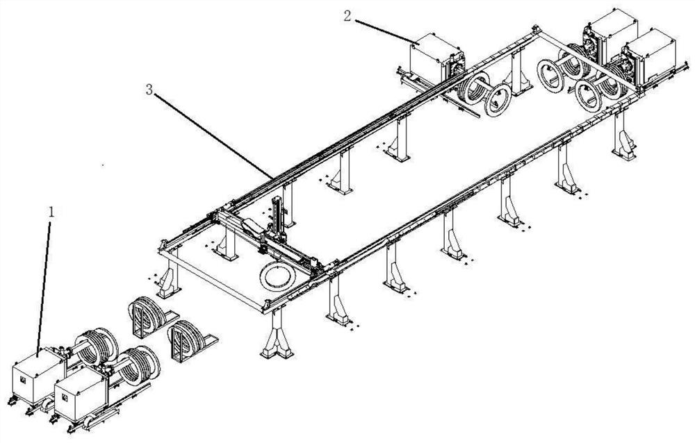
[0030] Such as figure 1 as shown, figure 1 It is a perspective view of the structure of the hoop detection system; the hoop detection system includes a loading and unstacking truck 1, an unloading stacking truck 2, and a hoop handling assembly 3, and the loading and unstacking truck 1 takes multiple The rings to be inspected are separated one by one, and the hoop handling assembly 3 grabs a single ring to be inspected on the loading and destacking truck 1 to continue detection and transport to the unloading stacker 2. The unloading stacker truck 2 takes the rings to be inspected on the hoop handling assembly 3 one by one, and stacks and arranges the rings to be inspected.
[0031] Specifically, the operation process of the hoop detection system: the operator places the rings to be inspected at a designated point. The support and separation component of the material destacking truck 1 passes through the center of the ring to be inspected to lift the ring to be inspected, the ...
Embodiment 2
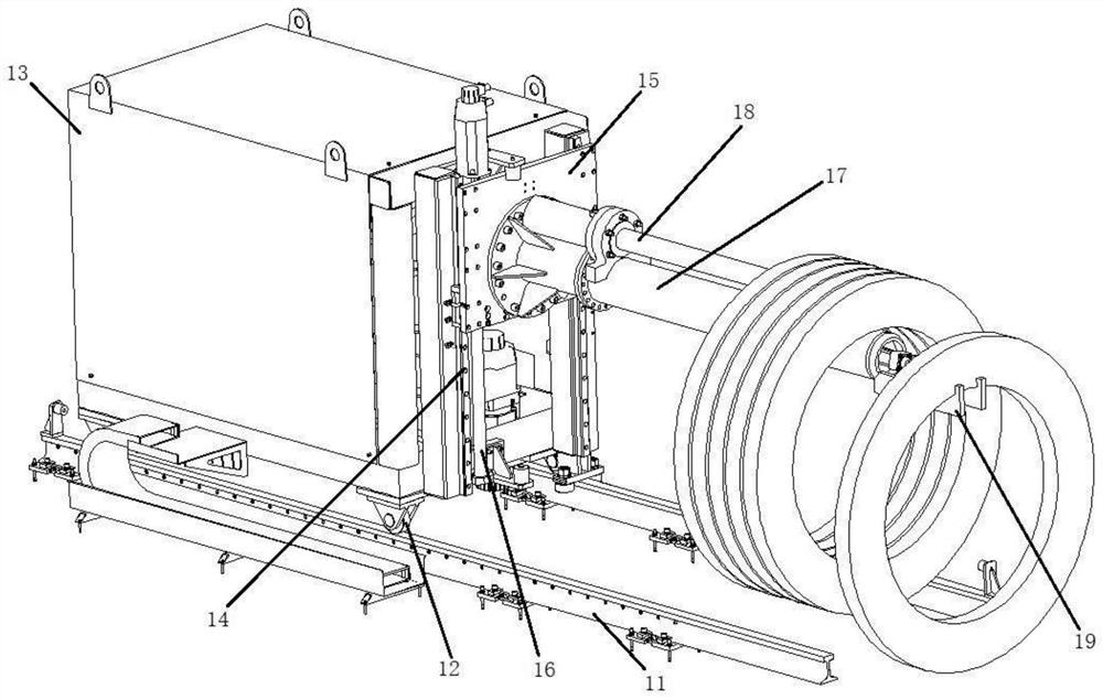
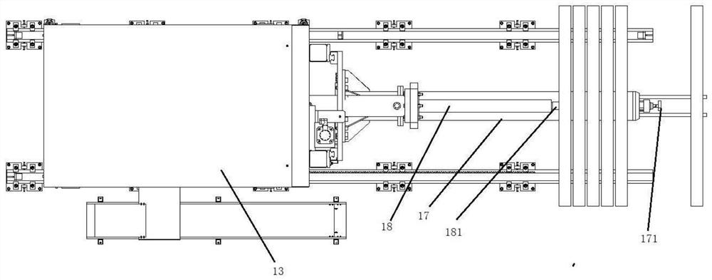
[0037] Such as figure 2 , image 3 as shown, figure 2 It is a three-dimensional view of the structure of the loading and destacking truck; image 3 It is a top view of the structure of the loading and destacking vehicle; the loading and destacking vehicle 1 includes a destacking ground guide assembly, a destacking vehicle body 13, a destacking vertical adjustment assembly and a support separation assembly, and the destacking vehicle body 13 is arranged on the unstacking ground guide assembly, and the unstacking vehicle body 13 can be driven to move linearly on the ground through the unstacking ground guide assembly, and the support separation assembly is connected by the unstacking vertical adjustment assembly On the destacking car body 13, the vertical height of the support separation assembly can be adjusted through the destacking vertical adjustment assembly, so as to pass through the center of the ring to be inspected to realize the lifting and taking operation of the ...
Embodiment 3
[0052] Such as Figure 4 as shown, Figure 4 It is a partial structural view of the hoop handling assembly; the hoop handling assembly 3 includes a transport frame and a grabbing hand 31, the grabbing hand 31 is arranged on the transport rack, and the transport rack drives the The grabbing hand 31 moves, and the grabbing hand 31 grabs a single ring to be inspected on the loading and unstacking truck 1 .
[0053] The transport frame includes a structural assembly 32, a crossbeam assembly 33 and a vertical beam assembly 34, the structural assembly 32 is fixedly arranged on the ground, the crossbeam assembly 33 is connected with the structural assembly 32 through a support adjustment group 35, and the vertical The beam assembly 34 is connected to the cross beam assembly 33 through a cross beam adjustment group 36 , and the grabbing hand 31 is connected to the vertical beam assembly 34 through a vertical beam adjustment group 37 . The support adjustment group 35 adjusts the move...
PUM
 Abstract
Description
Claims
Application Information