Plastic mold with edge material cutting device

A technology of cutting device and plastic mold, applied in the field of plastic mold, can solve the problems of low cutting strength and cumbersome process, and achieve the effect of increasing cutting strength and avoiding slice breakage

Inactive Publication Date: 2019-01-04
HUANGSHAN MINGSHENG DIE MATERIAL CO LTD
View PDF0 Cites 0 Cited by
  • Summary
  • Abstract
  • Description
  • Claims
  • Application Information

AI Technical Summary

Problems solved by technology

[0003] The purpose of the present invention is to solve the shortcomings of cumbersome procedures and

Method used


Image

  • Plastic mold with edge material cutting device
  • Plastic mold with edge material cutting device
  • Plastic mold with edge material cutting device

Examples


Embodiment Construction

[0015] The following will clearly and completely describe the technical solutions in the embodiments of the present invention with reference to the accompanying drawings in the embodiments of the present invention. Obviously, the described embodiments are only some, not all, embodiments of the present invention.

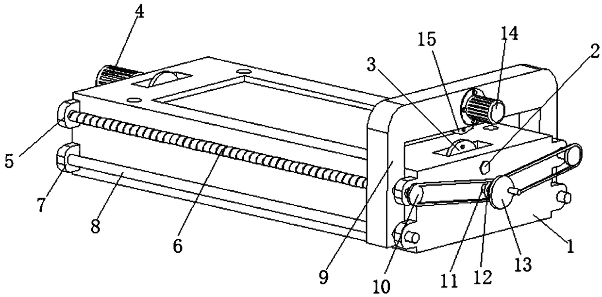
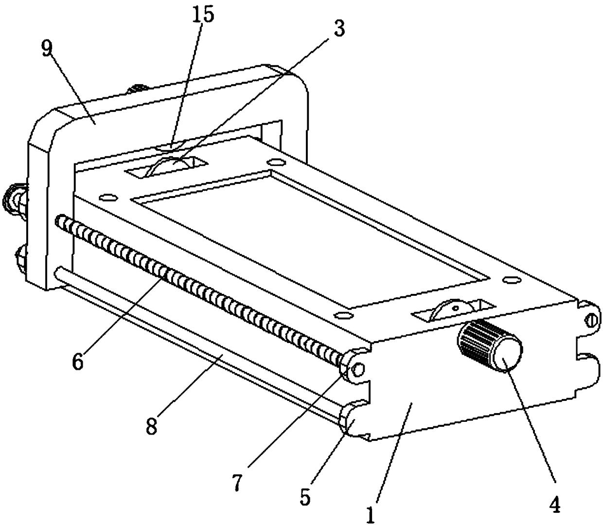
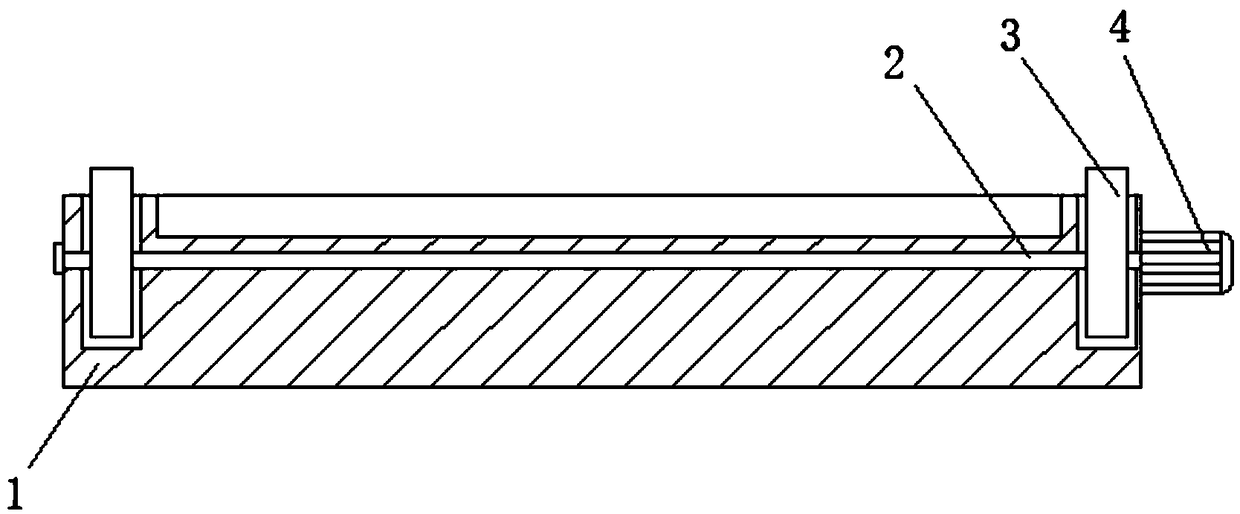
[0016] refer to Figure 1-3 , a plastic mold with an edge material cutting device, comprising a lower mold 1, the interior of the lower mold 1 is provided with a rotating shaft 2, the rotating shaft 2 runs through the lower mold 1 and is rotationally connected with the lower mold 1, the two ends of the rotating shaft 2 are There is a first slice 3, and the two first slices 3 are fixedly connected to the rotating shaft 2, and the two first slices 3 are arranged inside the lower mold 1, and one end of the lower mold 1 is provided with a first motor 4 , the first motor 4 is fixedly connected to the lower die 1, the output shaft of the first motor 4 of the lower die 1 ru...


PUM


Abstract

The invention relates to the technical field of plastic molds, in particular to a plastic mold with an edge material cutting device. The plastic mold comprises a lower die; a rotating shaft is arranged in the lower die; first cutters are arranged at both ends of the rotating shaft; a first motor is arranged at one end of the lower die; first ear seats are arranged on the two sides of the lower die; a threaded rod is arranged between the two first ear seats; second ear seats are arranged under the first ear seats; a guide rod is arranged between the two second ear seats; a sliding support seatis arranged on the threaded rod; a first driving wheel is arranged at one end of the threaded rod; a coupling shaft is arranged on the side wall of the low die; a second driving wheel is arranged on the coupling shaft; a hand wheel is arranged at one end of the coupling shaft; a second motor is arranged on the side wall of the sliding support seat; a second cutter is arranged at the interior partof the sliding support seat; and the output shaft of the second motor passes through the side wall of the sliding support seat and is fixedly connected with the second cutter. The plastic mold has strong practicability and is worth popularizing.

Description

technical field [0001] The invention relates to the technical field of plastic molds, in particular to a plastic mold with an edge material cutting device. Background technique [0002] Molds, various molds and tools used in industrial production for injection molding, blow molding, extrusion, die-casting or forging forming, smelting, stamping, etc. to obtain the required products, in short, molds are tools used to make shaped objects , this tool is composed of various parts, different molds are composed of different parts, the mold has a specific contour or inner cavity shape, and the contour shape with a cutting edge can be used to separate the blank according to the contour line shape (punching), The shape of the cavity can be used to obtain the corresponding three-dimensional shape of the blank. The mold generally includes two parts: a movable mold and a fixed mold (or a punch and a concave mold). However, the width of the forming mold of some sheet products is generall...

Claims


Application Information

Patent Timeline
IPC IPC(8): B29C37/02
CPCB29C37/02
Inventor 董德胜
Owner HUANGSHAN MINGSHENG DIE MATERIAL CO LTD
Why Eureka
Try Eureka