Duct-type ship propeller

A propeller, ducted technology, applied in the direction of rotary propeller, hull design, rotating propeller, etc., can solve the problems of unstable sailing and increase power loss, achieve smooth sailing, reduce power loss and improve safety and service life

Active Publication Date: 2019-01-04
ZHEJIANG WEHIGH TECH CO LTD
View PDF11 Cites 1 Cited by
  • Summary
  • Abstract
  • Description
  • Claims
  • Application Information

AI Technical Summary

Problems solved by technology

[0003] The purpose of the present invention is to overcome the current ships with external propellers and rudders, which have the disadvantages of large wave-making resistance and increased power loss when sailing at

Method used


Image

  • Duct-type ship propeller
  • Duct-type ship propeller
  • Duct-type ship propeller

Examples


Embodiment 1

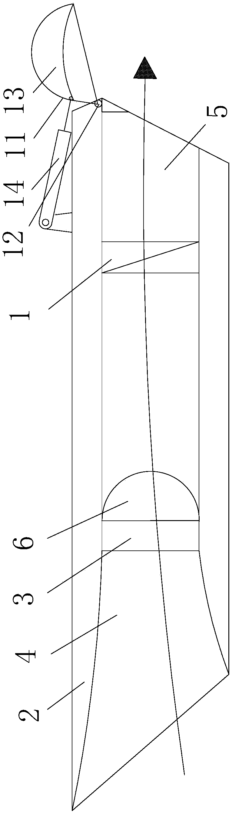
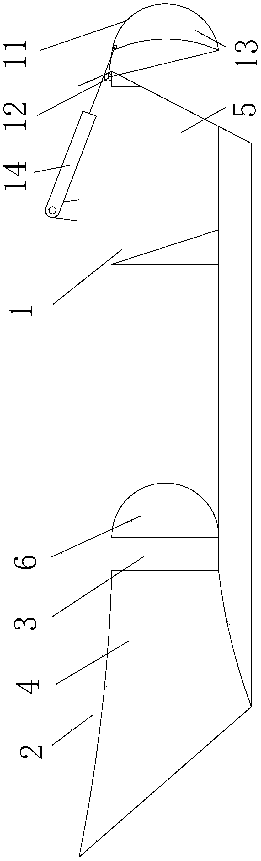
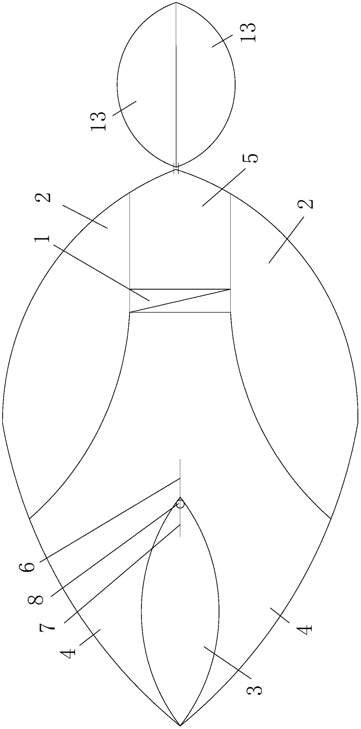
[0026] Example 1, as attached figure 1 Attached Figure 7 Shown: a ducted ship propeller, including: a propeller 1, a shell 2 arranged in the lower part of the hull (not shown in the figure), a partition 3 arranged in the shell 2, symmetrically arranged in the middle Two inlets 4 on both sides of the partition 3 and through the front end of the housing 2, a built-in rudder arranged on the intermediate partition 3, and an outlet 5 at the rear end of the housing 2 and the front end communicates with the rear end of the inlet 4 ; The propeller 1 is located in the water outlet 5; the lower side of the inlet end of the water inlet 4 is lower than the no-load waterline of the hull; the horizontal median plane of the water inlet 4 is lower than the full-load waterline of the hull.

[0027] The built-in rudder includes: a middle rudder plate 6, a middle lever 7 connected to the upper end of the middle rudder plate 6 at the rear end, and a front rudder shaft 8 whose upper end is screwed to...

Embodiment 2

[0033] Example 2, as attached Figure 8 Shown, and see attached figure 1 Attached Figure 4 , Attached Figure 7 : A ducted ship propeller, comprising: a propeller 1, a shell 2 arranged in the lower part of the hull, two laterally symmetrical water channels 15 arranged in the shell 2 and passing through the front end of the shell 2; The front end and the rear end correspond to the front and rear ends of the shell 2 through one by one; there are two propellers 1; the two propellers 1 are arranged in the two water channels 15 one by one; the lower side of the inlet end of the water channel 15 is lower than the hollow of the hull Load waterline; the horizontal median of channel 15 is lower than the full load waterline of the hull.

[0034] The ducted ship propulsion also includes: an emergency stop and reverse rudder 11 formed at the rear end of the shell 2 and composed of two symmetrically arranged sub-rudders; the sub-rudder includes: one end and the upper end of the shell 2 are c...


PUM


Abstract

The invention relates to a duct-type ship propeller comprising: a propeller, a hull arranged at the lower part of the hull, a middle partition arranged in the hull, two inlet channels symmetrically arranged at the two sides of the middle partition and penetrating with the front end of the hull, a built-in rudder arranged on the middle partition, and an outlet channel arranged at the rear end of the hull and communicated with the front end of the inlet channel. The propeller is located in the outlet channel; the underside of the inlet end of the inlet is below the unloaded draft line of the hull. The channel-type ship propeller enters the water flow from two inlet channels connected with the front end of the hull during navigation to reduce the resistance and squeeze of the bow of the shipby the water, and the wave-making resistance is small during high-speed navigation to reduce the power loss, and the ship sails smoothly; through the built-in rudder to adjust the ship navigation direction, propeller, built-in rudder inside the shell will not hang fishing nets, aquatic plants, etc., and will not collide with the reef, etc. to improve safety and service life.

Description

Technical field [0001] The invention relates to the field of ships, in particular to a ducted ship propeller. Background technique [0002] The main resistance of a ship during navigation is frictional resistance, wave resistance, and viscous pressure resistance, and the main constraint on high-speed navigation of a ship is the wave-making resistance that can reach more than 50% of the total resistance; the wave-making resistance is the front of the hull pushing away during the forwarding process. During this process, because the water in the bow of the ship is squeezed and arched upwards, the bow wave generated further increases the wave resistance and collides with other normal waves. Therefore, the ship The faster the speed, the greater the wave resistance; ships with external propellers and stern rudders have the disadvantages of high wave resistance and increased power loss during high-speed navigation, and the navigation is not stable enough; therefore, a design of a high-s...

Claims


Application Information

Patent Timeline
IPC IPC(8): B63H1/14
CPCB63H1/14Y02T70/10
Inventor 付小华
Owner ZHEJIANG WEHIGH TECH CO LTD
Why Eureka
Try Eureka