Centrifugal device of flange nut

A flange nut and centrifugal device technology, applied in coating, metal material coating process, hot dip plating process, etc., can solve the problems of low safety and poor efficiency of manual separation of plating solution, and achieve a high degree of automation and structure. reasonable effect

Pending Publication Date: 2019-01-04
嘉兴祥盛汽车配件制造有限公司
View PDF0 Cites 1 Cited by
  • Summary
  • Abstract
  • Description
  • Claims
  • Application Information

AI Technical Summary

Problems solved by technology

[0003] The purpose of the present invention is to overcome the deficiencies of the above-mentioned prior art and provide a centrifugal device for flange nuts, which aims to solve the technical problems of low safety and poor efficiency of manual separation of plating solution in the prior art

Method used


Image

  • Centrifugal device of flange nut
  • Centrifugal device of flange nut
  • Centrifugal device of flange nut

Examples


Embodiment Construction

[0017] In order to make the objectives, technical solutions and advantages of the present invention clearer, the following further describes the present invention in detail through the accompanying drawings and embodiments. However, it should be understood that the specific embodiments described here are only used to explain the present invention, and are not used to limit the scope of the present invention. In addition, in the following description, descriptions of well-known structures and technologies are omitted to avoid unnecessarily obscuring the concept of the present invention.

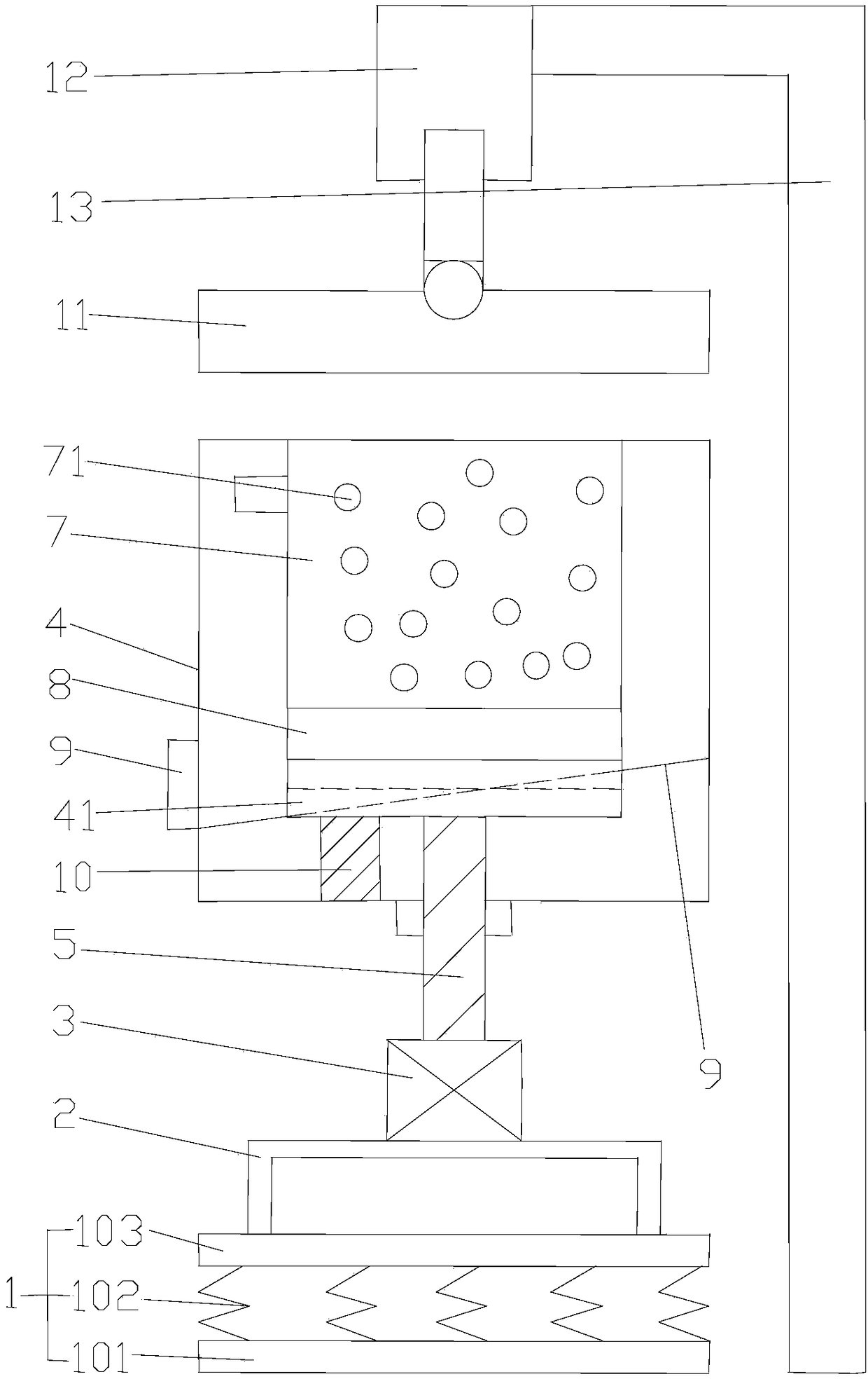
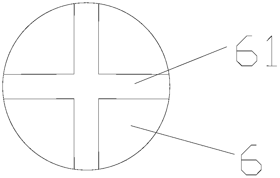
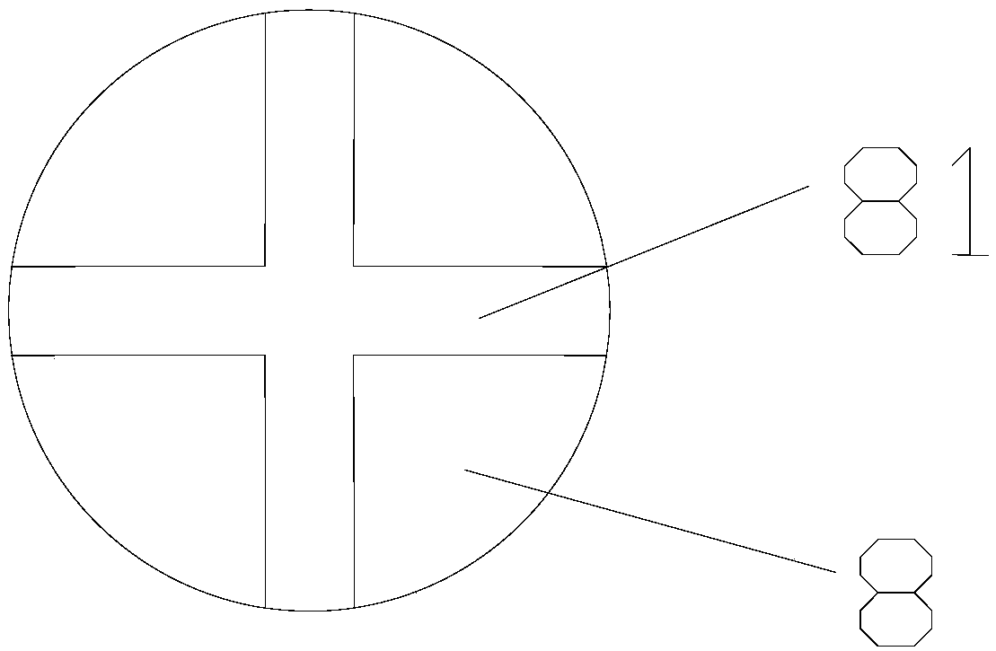
[0018] Refer to figure 1 , figure 2 with image 3 , The embodiment of the present invention provides a centrifugal device for flange nuts, including a vibration device 1, a centrifuge frame 2, a centrifugal motor 3, a centrifuge cylinder 4, a rotating shaft 5, a lower clamping disc 6, a centrifugal inner cylinder 7, an upper clamping disc 8, The chip guide 9, the elastic gravity sensor 10, the ...


PUM


Abstract

The invention provides a centrifugal device of a flange nut. The centrifugal device of the flange nut comprises a vibration device, a centrifugal frame, a centrifugal motor, a centrifugal cylinder, arotating shaft, a lower clamping disk, a centrifugal inner cylinder, an upper clamping disk, a scrap guide plate, an elastic gravity sensor, a flip cover, an electric telescopic rod and a supporting frame; the vibration device is connected with the centrifugal frame; the centrifugal frame is connected with a centrifugal motor; the centrifugal motor is connected with a rotating shaft; the part above the rotating shaft is connected with the lower clamping disk; the lower clamping disk is arranged in the centrifugal cylinder; the centrifugal inner cylinder is arranged in the centrifugal cylinder;the upper clamping disk is in up-and-down fit connection with the lower clamping disk; the scrap guide plate is arranged in the centrifugal cylinder; the elastic gravity sensor is arranged between the lower clamping disk and the cylinder bottom of the centrifugal cylinder; the flip cover is arranged over the centrifugal cylinder; the flip cover is connected with the electric telescopic rod; the telescopic rod is connected with the supporting frame; the elastic gravity sensor is in communication connection with the electric telescopic rod, automatic separation is realized, and the efficiency is high.

Description

【Technical Field】 [0001] The invention relates to the technical field of a flange nut galvanizing process, in particular to the technical field of a centrifugal device of a flange nut. 【Background technique】 [0002] Flange nuts, also known as gasket nuts, spline nuts, hexagonal flange nuts, flange nuts, etc., are mostly used in pipe connections or workpieces that require increased nut contact surfaces. The current flange nuts are galvanized It is necessary to separate the excess plating solution. Due to the low safety and low efficiency of high-temperature manual separation, it is necessary to propose a centrifugal device for flange nuts. [Content of the invention] [0003] The purpose of the present invention is to overcome the above-mentioned shortcomings of the prior art and provide a flange nut centrifugal device, which aims to solve the technical problems of low safety and low efficiency of manual separation of plating solutions in the prior art. [0004] In order to achieve ...

Claims


Application Information

Patent Timeline
IPC IPC(8): C23C2/14C23C2/06
CPCC23C2/06C23C2/14
Inventor 冯董妹
Owner 嘉兴祥盛汽车配件制造有限公司
Why Eureka
Try Eureka