Construction method for demountable and mountable concrete shear wall with adjustable bearing capacity

A concrete shear wall, construction method technology, applied in the direction of walls, building components, buildings, etc., can solve the problem of not being able to be reused

Pending Publication Date: 2019-01-04
TONGJI UNIV
View PDF0 Cites 1 Cited by
  • Summary
  • Abstract
  • Description
  • Claims
  • Application Information

AI Technical Summary

Problems solved by technology

[0003] In view of the above-mentioned shortcomings of the prior art, the object of the present invention is to provide a construction method of a detachable concrete shear wall with adjustable bearing capacity, which is used to solve the problem that the existing monolithic concrete shear wall in the prior art cannot To solve the problem of repeated use, provide a reusable detachable concrete shear wall, and meet the needs of different bearing capacity

Method used


Image

  • Construction method for demountable and mountable concrete shear wall with adjustable bearing capacity
  • Construction method for demountable and mountable concrete shear wall with adjustable bearing capacity
  • Construction method for demountable and mountable concrete shear wall with adjustable bearing capacity

Examples


Embodiment 1

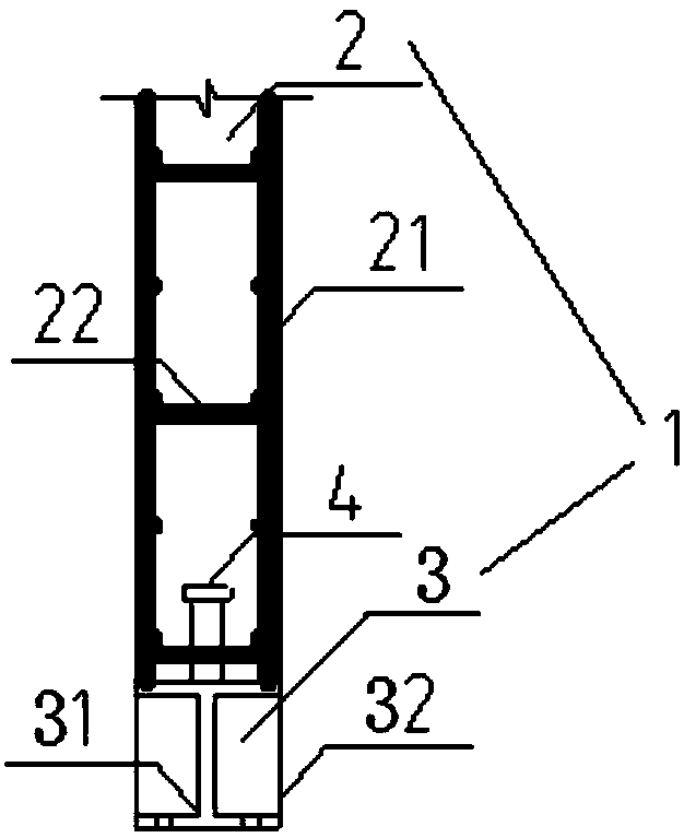
[0128] To prepare a detachable concrete shear wall with adjustable bearing capacity, the concrete wall section is set first. The section size of the concrete wall section needs to bear the same load as that of the integral concrete shear wall. Among the section dimensions of the concrete wall section, the length ( L) is 1000-3000mm, width (W) is 150-300mm. Bind longitudinal steel bars and transverse stirrups in the concrete wall section to make a reinforcement cage, the longitudinal reinforcement and transverse stirrups are evenly distributed in the reinforcement cage, the distance between the adjacent longitudinal reinforcements is 80-200mm, and the adjacent transverse stirrups The spacing between them is 80-200mm.

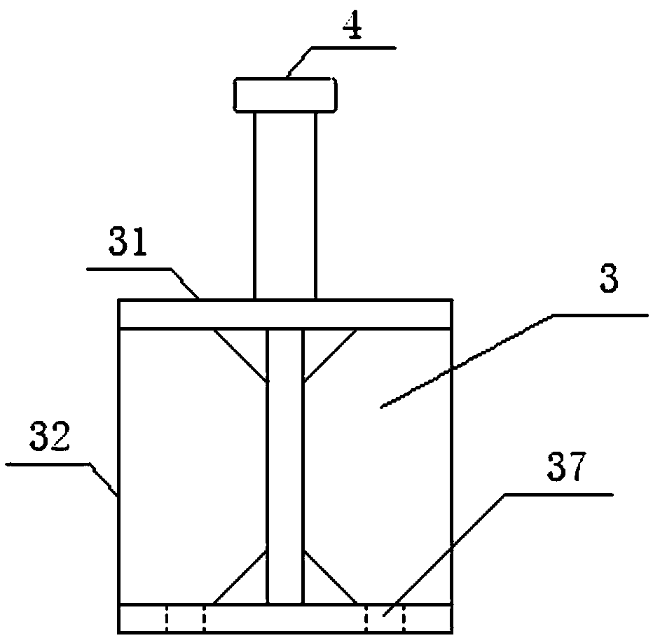
[0129] Then, set a plurality of studs in the concrete wall section, the diameter φ of the studs is 16-18mm, and the length is 40-80mm. The studs are evenly distributed within the concrete wall section with a spacing of 90-110mm between adjacent studs.

[0130] ...

Embodiment 2

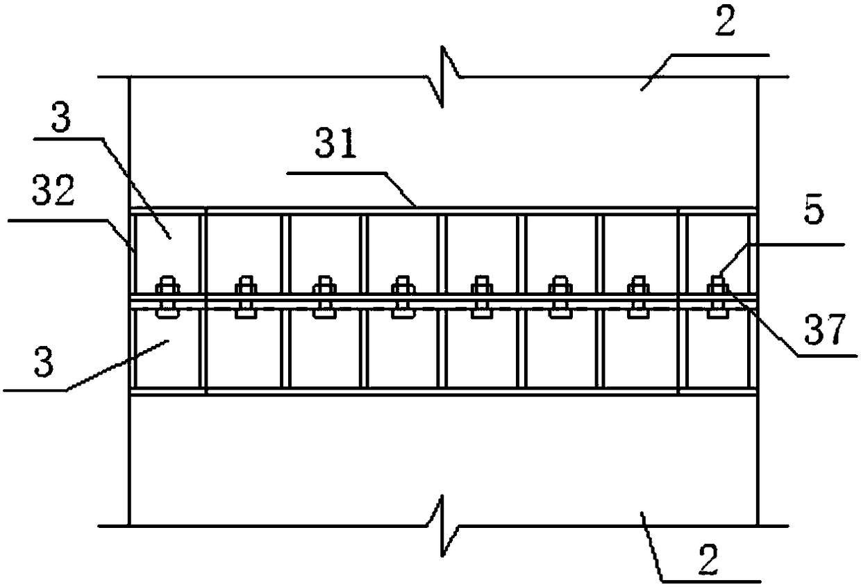
[0137] According to the construction method in Example 1, a detachable concrete shear force example wall was made, using C30 concrete, the height of the wall was 2400mm, the length of the wall was 800mm, and the width was 200mm; the connecting nodes used 8.8 grade M14 bolts, a total of two There are 16 bolts in a row, the spacing along the length direction of the wall is 100mm, and the spacing along the width direction of the wall is 50mm. Relevant performance tests were carried out on this example wall, and relevant performance tests were carried out on the currently conventional monolithic concrete shear walls of the same size. The relevant performance test results of the two are shown in Table 1.

[0138] Table 1 Comparison of performance indicators

[0139] project

[0140] It can be seen from Table 1 that the cross-sectional bending bearing capacity and cross-sectional shearing bearing capacity of the detachable concrete shear wall of the present invention are s...


PUM

PropertyMeasurementUnit
Lengthaaaaaaaaaa
Widthaaaaaaaaaa
Diameteraaaaaaaaaa

Abstract

The invention provides a demountable and mountable concrete shear wall with the adjustable bearing capacity, and further provides a construction method and application of the demountable and mountableconcrete shear wall with the adjustable bearing capacity. The demountable and mountable concrete shear wall comprises two or more shear wall components. Each shear wall component comprises a concretewall section and a profile steel connecting section. The profile steel connecting sections are arranged at the ends of the concrete wall sections and fixedly connected with the concrete wall sections. The adjacent shear wall components are detachably connected through the profile steel connecting sections. According to the construction method of the demountable and mountable concrete shear wall with the adjustable bearing capacity, compared with an integral casting concrete shear wall, the demountable and mountable concrete shear wall prepared through the construction method has the same reciprocating load bearing capacity and can be demounted, and multi-time splicing for reutilization is achieved.

Description

technical field [0001] The invention belongs to the technical field of structural engineering and relates to a construction method of a detachable concrete shear wall with adjustable bearing capacity. Background technique [0002] The increasing impact of construction on the environment calls for the sustainable use of concrete. To implement the international "3R" concept of Reduce, Reuse, and Recycle, concrete structures need to be reused in terms of materials and components. Directly reusing concrete components is not only efficient but also consumes less energy. At present, the prefabricated assembly structure is actively promoted in China, so a detachable concrete shear wall is needed, which not only adapts to the component form of the prefabricated assembly concrete structure, but also can be disassembled when the structure is dismantled and can be reassembled in a new building. This facilitates the assembly and disassembly of concrete components. Contents of the in...

Claims


Application Information

Patent Timeline
IPC IPC(8): E04B1/343E04B2/58
CPCE04B1/34315E04B2/58
Inventor 肖建庄卫凯华丁陶
Owner TONGJI UNIV
Why Eureka
Try Eureka