Sluice valve with high sealing property

A high-sealing and high-performance technology, applied in shaft seals, sliding valves, valve details, etc., can solve the problem of reducing the transmission force of the valve stem, achieve the effect of reducing the transmission force of the polished rod, preventing the thread from being stuck, and improving the sealing performance

Inactive Publication Date: 2019-01-04
自贡诚鑫阀门有限公司
View PDF3 Cites 0 Cited by
  • Summary
  • Abstract
  • Description
  • Claims
  • Application Information

AI Technical Summary

Problems solved by technology

[0003] In order to overcome the above-mentioned technical defects, the purpose of the present invention is to provide a method to improve the sealing performance of the sealing surface. The valve stem changes from the original spiral rise to the linear slide rise. Reduce the driving force of the valve stem, improve the sealing performance of the valve cover at the same time, effectively prevent the top bending of the valve stem due to excessive medium pressure, and the push-type seal of the gate plate improves the sealing performance between the gate plate and the valve seat. gate

Method used


Image

  • Sluice valve with high sealing property
  • Sluice valve with high sealing property
  • Sluice valve with high sealing property

Examples


Embodiment 1

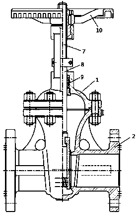
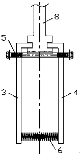
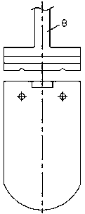
[0019] Example 1, such as Figure 1 to Figure 3 As shown in , the present invention is a gate valve with high sealing performance, including a valve stem, a valve cover 1, a valve seat 2 and a gate plate; the valve cover 1 encapsulates the fixedly connected valve stem and gate plate in the valve seat 2, The valve stem is the sealing actuator of the gate; the valve stem drives the gate to move up and down to open and close the valve seat 2; the gate is a double gate structure composed of a left gate 3 and a right gate 4; the left gate 3 And the upper part of the right flashboard 4 is fixed by the bolt 5, and the inner side of the lower part is elastically supported by the spring 6.

[0020] The integral gate in the prior art is usually supported by castings, and its compression is at most 3%, and the fluid medium on both sides does not produce rebound after compression, so the seal of the gate will be poor. The gate valve in the present invention has a structure of single gate...

Embodiment 2

[0022] Example 2, such as figure 1 and Figure 4 As shown in , the valve rod is composed of a fixedly connected screw rod 7 and a polished rod 8; the screw rod 7 rises or falls relative to the threaded rotation of the valve cover 1, and the polished rod 8 rises or falls linearly relative to the valve cover 1; the lower end of the polished rod 8 is connected to the The top of the gate plate is snapped connected; the fixed connection between the screw rod 7 and the polished rod 8 is a clamp connection, a hook connection or a shrink-fit connection; a non-metallic sealing packing 9 is provided between the polished rod 5 and the valve cover 1, The non-metal sealing packing 9 is made of flexible graphite or polytetrafluoroethylene.

[0023] Three fixed connection methods of screw and polished rod: such as figure 1 As shown in , the connection mode between the screw rod 7 and the polished rod 8 is a clamp connection, that is, the screw rod 7 and the polished rod 8 are clamped and f...


PUM


Abstract

The invention discloses a sluice valve with high sealing property. The sluice valve with high sealing property comprises a valve rod, a valve bonnet, a valve seat and a flashboard. The valve rod and the flashboard which are fixedly connected are sealed in the valve seat by the valve bonnet. The flashboard is driven to move up and down by the valve rod, and the valve seat is started and stopped bythe valve rod. The flashboard is of a dual-flashboard structure composed of a left flashboard and a right flashboard. Upper portions of the left flashboard and the right flashboard are fixed through bolts, and inner sides of lower portions of the left flashboard and the right flashboard are in elastic support through springs. According to the dual-flashboard structure of the sluice valve, angle limiting adjustment of the upper portions are achieved through bolts, and adjustment support of the lower portions are achieved through springs. Pressing force is added by the springs. Pushing and pressing type sealing is formed. Good sealing property on a sealing surface between the flashboard and the valve seat is always kept. A novel type nonmetal sealing filler is adopted, sealing property of the valve bonnet is improved, and meanwhile, polished rod transmission force can also be reduced. A sectional type fixing method is adopted by the valve rod; a former form of spiral rising is changed into a form of straight rising; and torque transmission is changed into stretching sliding transmission. According to the sluice valve with the high sealing property, possibility that the valve rod bends is directly eliminated; and failure of a valve in an existing design is effectively and completely eradicated.

Description

technical field [0001] The invention relates to the technical field of gate valves, in particular to a gate valve with high sealing performance. Background technique [0002] Gate valve is also called gate valve. The opening and closing part of the gate valve is a gate. The direction of movement of the gate is perpendicular to the direction of the fluid. The gate valve can only be fully opened and fully closed, and cannot be adjusted or throttled. The present invention mainly solves the following problems in current domestic gate valves: 1. Large switching torque: The traditional valve stem packing sealing method of gate valves is that the packing is formed by the extrusion deformation force of the packing gland and the physical deformation of the bolts to cover the valve stem seal. The disadvantage is that the bolt tightening is very random and difficult to control by the workers. Overloading and tightening will occur at the use site. The clamping force of the packing defor...

Claims


Application Information

Patent Timeline
Patent Type & Authority Applications(China)
IPC IPC(8): F16K3/02F16K3/314F16K41/02
CPCF16K3/02F16K3/0236F16K3/314F16K41/02
Inventor 张柔依张剑
Owner 自贡诚鑫阀门有限公司
Why Eureka
Try Eureka