
Simulation test engine in high-speed rotation stage

A simulation test, high-speed rotation technology, applied in the direction of engine testing, machine/structural component testing, instruments, etc., can solve the problems of process danger and low safety factor, and achieve the effect of reasonable structure, stable operation and avoiding engine explosion

Inactive Publication Date: 2019-01-04
NANJING UNIV OF SCI & TECH
View PDF5 Cites 0 Cited by
  • Summary
  • Abstract
  • Description
  • Claims
  • Application Information

AI Technical Summary

Problems solved by technology

[0003] At present, the testing of various characteristic parameters of solid rocket motors during high-speed rotation is mainly done through high-speed rotary table tests. The traditional test engines are filled with grains. During the test, ignition and grain combustion are required. The process is very dangerous. The safety factor is very low, so a test simulation engine that can replace the grain combustion and greatly improve the safety and reliability can be equivalent to test the thrust pressure.

Method used


Image

  • Simulation test engine in high-speed rotation stage
  • Simulation test engine in high-speed rotation stage
  • Simulation test engine in high-speed rotation stage

Examples


Embodiment Construction

[0024] Below in conjunction with accompanying drawing of description, the present invention will be further described.

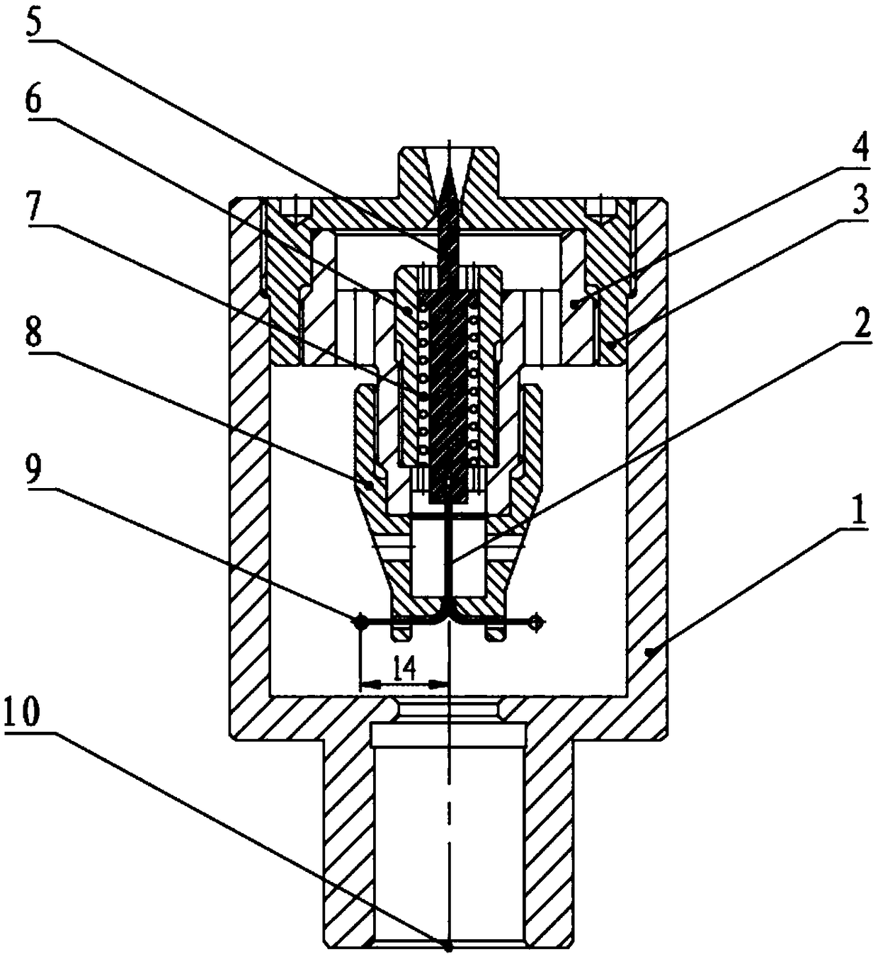
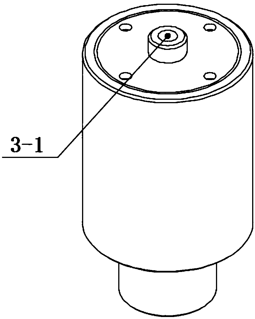
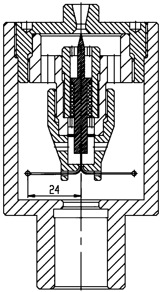
[0025] combine Figure 1-7 , a simulation test engine in a high-speed rotary table, including a test engine casing 1, two identical nylon wires 2, a blocking cover 3, a rotating shaft sleeve 4, a firing pin 5, a fixed sleeve 6, a spring 7, a rotating base 8, Two identical small balls 9, the engine casing 1 is a hollow structure with openings at both ends, the blocking cover 3 is fixed on the inner side of the upper end of the engine casing 1, and the top center of the blocking cover 3 includes a nozzle structure 3 -1 is used to simulate an engine nozzle, and the rotating shaft sleeve 4 is connected with the internal thread of the inner wall of the blocking cover 3 through an external thread. The rotating shaft sleeve 4 includes a central through hole, and the fixed sleeve 6 is sleeved In the central through hole of the rotating shaft sleeve 4, the firing pi...


PUM

PropertyMeasurementUnit
Diameteraaaaaaaaaa

Abstract

The invention discloses a simulation test engine in a high-speed rotation stage. The simulation test engine comprises a test engine shell body, nylon ropes, a plug cover, a rotating shaft sleeve, a firing pin, a fixing sleeve, a spring, a rotating base and small aluminum balls, wherein the plug cover is connected with the test engine shell body in a threaded manner; the rotating shaft sleeve is connected with the plug cover in a threaded manner; the rotating base is connected with the rotating shaft sleeve in a threaded manner; the spring is arranged inside the fixing sleeve and on the outer side of the firing pin; the test engine shell body, the rotating shaft sleeve, the fixing sleeve, the rotating base, the firing pin and the spring are arranged on the same axis; and one end of each nylon rope is connected with the corresponding aluminum ball, the other end passes through an earring through hole at the lower part of the rotating base and is connected with a bottom surface positioning hole at the lower part of the firing pin. Through injecting air with certain pressure by means of an air inlet passage at the lower end surface of the test engine shell body, the test engine rotatesat a high speed to generate a centrifugal force so that the small balls drive the nylon ropes to generate transverse displacement, thus the firing pin moves downwardly so that the throat area changes, thereby causing the effect of changing thrust of the test engine and pressure in a combustion chamber.

Description

technical field [0001] The invention relates to the technical field of engine simulation experiments, in particular to a simulation test engine in a high-speed rotary table. Background technique [0002] In the development of weapon systems such as turbo rockets and bottom-row extended-range projectiles, the projectiles often rotate at high speeds during the acceleration stage of the internal trajectory. The state of high-speed rotation. High-speed rotation will have a greater impact on the performance parameters of the solid rocket motor such as thrust and pressure, making the combustion chamber characteristics of the solid rocket motor significantly different from those in the non-rotating state. [0003] At present, the testing of various characteristic parameters of solid rocket motors during high-speed rotation is mainly done through high-speed rotary table tests. The traditional test engines are filled with grains. During the test, ignition and grain combustion are re...

Claims


Application Information

Patent Timeline
IPC IPC(8): G01M15/00
CPCG01M15/00
Inventor 王启凡余陵蔡文祥王纪林
Owner NANJING UNIV OF SCI & TECH
Learn More