
Torque loading test fixture for curved surface

A tooling and curved surface technology, applied in the field of curved surface loading torsion test tooling, can solve problems such as affecting test accuracy, unreal data, test failure, etc., and achieve the effect of eliminating low matching accuracy, real data and simple structure

Pending Publication Date: 2019-01-04
AVIC STANDARD PARTS MFG
View PDF0 Cites 0 Cited by
  • Summary
  • Abstract
  • Description
  • Claims
  • Application Information

AI Technical Summary

Problems solved by technology

However, this fit mode is usually applied in the torsion test where the loading end surface of the part is a plane. Its disadvantage is that when the loading surface of the part is a curved surface, the contact area between the plane loading gasket and the part is very small, which will affect the test during the loading process. Accuracy, destroying the contact surface of parts will cause the test to fail, resulting in untrue data and inconvenient loading and unloading

Method used


Image

  • Torque loading test fixture for curved surface
  • Torque loading test fixture for curved surface

Examples


Embodiment Construction

[0015] In the following, with reference to the drawings and preferred embodiments, the specific implementation, features and functions of the curved surface torsion test tool according to the present invention will be described in detail as follows.

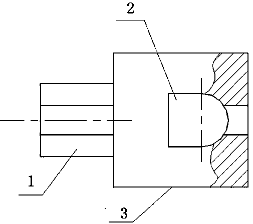
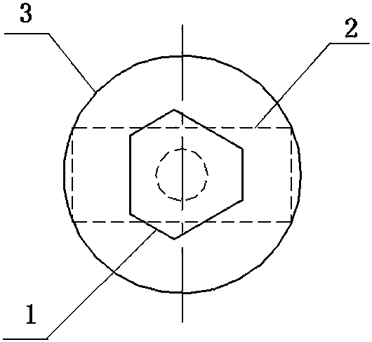
[0016] see Figure 1 to Figure 2 , a curved torsion test tooling of the present invention includes a chuck 1, a cavity 2, and a tooling seat 3, wherein: the two ends of the tooling seat 3 are respectively provided with a chuck 1 and a tooling seat 3.

[0017] The chuck 1, cavity 2 and tooling seat 3 are integral structural parts.

[0018] The chuck 1 is a triangular prism structure.

[0019] The die cavity 2 is a die cavity conforming to the size and shape of the bearing curved surface of the part, and the end face is a plane.

[0020] The materials of the chuck 1, the cavity 2 and the tooling seat 3 are alloy steel.

[0021] When in use, the collet 1 is clamped on the torque machine, the part is put into the cavity 2, and the...


PUM


Abstract

The invention discloses a torque loading test fixture for a curved surface. The torque loading test fixture comprises chucks (1), a cavity (2) and a fixture seat (3), and is characterized in that thechucks (1) are respectively arranged at two ends of the fixture seat (3). The torque loading test fixture is low in cost, convenient to use and simple in structure.

Description

technical field [0001] The invention belongs to the technical field of torsion tooling, in particular to a curved surface loading torsion test tooling applied to a part with a curved loading end surface. Background technique [0002] Torsion tooling is an auxiliary tooling widely used in torsion tests. Usually, the cavity of the torsion tooling will restrict two or more degrees of freedom of the test part, so that the part can rotate. If it needs to be loaded, it can be loaded with a loading washer. However, this fit mode is usually applied in the torsion test where the loading end surface of the part is a plane. Its disadvantage is that when the loading surface of the part is a curved surface, the contact area between the plane loading gasket and the part is very small, which will affect the test during the loading process. Accuracy, damage to the contact surface of the parts will cause the test to fail, resulting in untrue data and inconvenient loading and unloading. Con...

Claims


Application Information

Patent Timeline
Patent Type & Authority Applications(China)
IPC IPC(8): G01N3/02G01N3/22
CPCG01N3/02G01N3/22
Inventor 寇明肖文英邱明娟高振宇
Owner AVIC STANDARD PARTS MFG
Learn More