Lower detection and inspection instrument for high-speed railway vehicle
A technology of inspection instrument and high-speed rail, which is applied in the direction of instruments, measuring devices, scientific instruments, etc., can solve the problems of long inspection and maintenance time period, difficult operation of the handle, etc., and achieve the effect of easy control, free expansion and sliding, and easy sliding distance
- Summary
- Abstract
- Description
- Claims
- Application Information
AI Technical Summary
Problems solved by technology
Method used
Image
Examples
Embodiment 1
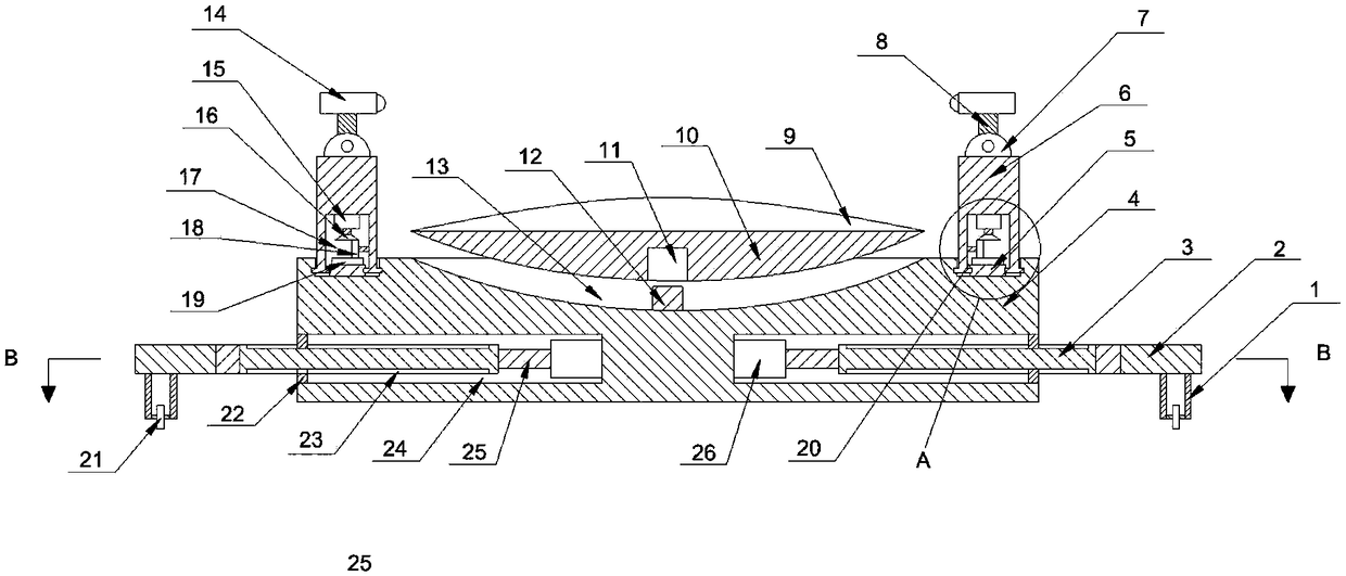
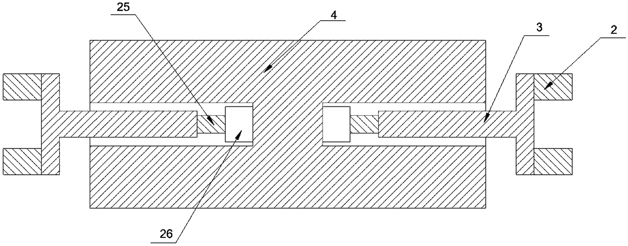
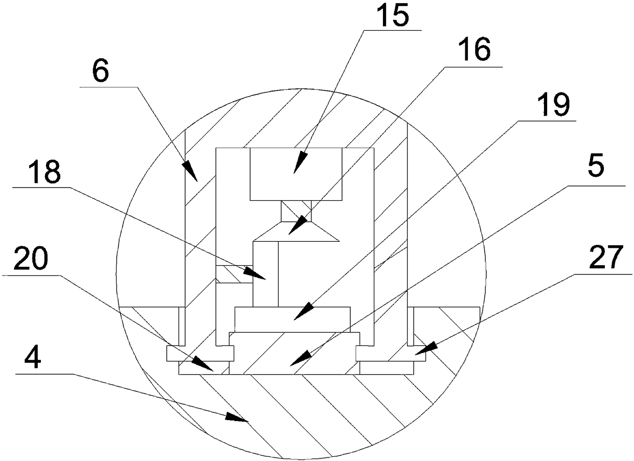
[0028] see figure 1 , figure 2 , image 3 , the detection and inspection instrument under the high-speed rail car, including the detection and inspection instrument main body 4, the convex mirror 9 with the mirror seat 10 is arranged above the detection and inspection instrument main body 4, and the detection and inspection instrument main body 4 upper surface on the outside of the convex mirror 9 is connected with a searchlight through a rotating mechanism 14. The lower part of the main body 4 of the detection and inspection instrument is symmetrically provided with a first cavity 24, and a telescopic mechanism is arranged in the first cavity 24, and the longitudinal part of the T-shaped sliding rod 3 of the telescopic mechanism slides and fits with the first cavity 24, The upper surface of the transverse part of the T-shaped slide bar 3 parallel to the detection and inspection instrument main body 4 is arranged outside the first cavity 24, and the two ends of the end surfa...
Embodiment 2
[0031] see figure 1 , figure 2 , image 3 , the detection and inspection instrument under the high-speed rail car, including the detection and inspection instrument main body 4, the convex mirror 9 with the mirror seat 10 is arranged above the detection and inspection instrument main body 4, and the detection and inspection instrument main body 4 upper surface on the outside of the convex mirror 9 is connected with a searchlight through a rotating mechanism 14. The lower part of the main body 4 of the detection and inspection instrument is symmetrically provided with a first cavity 24, and a telescopic mechanism is arranged in the first cavity 24, and the longitudinal part of the T-shaped sliding rod 3 of the telescopic mechanism slides and fits with the first cavity 24, The upper surface of the transverse part of the T-shaped slide bar 3 parallel to the detection and inspection instrument main body 4 is arranged outside the first cavity 24, and the two ends of the end surfa...
Embodiment 3
[0035] see figure 1 , figure 2 , image 3 , the detection and inspection instrument under the high-speed rail car, including the detection and inspection instrument main body 4, the convex mirror 9 with the mirror seat 10 is arranged above the detection and inspection instrument main body 4, and the detection and inspection instrument main body 4 upper surface on the outside of the convex mirror 9 is connected with a searchlight through a rotating mechanism 14. The lower part of the main body 4 of the detection and inspection instrument is symmetrically provided with a first cavity 24, and a telescopic mechanism is arranged in the first cavity 24, and the longitudinal part of the T-shaped sliding rod 3 of the telescopic mechanism slides and fits with the first cavity 24, The upper surface of the transverse part of the T-shaped slide bar 3 parallel to the detection and inspection instrument main body 4 is arranged outside the first cavity 24, and the two ends of the end surfa...
PUM
 Abstract
Description
Claims
Application Information
 - R&D
- Intellectual Property
- Life Sciences
- Materials
- Tech Scout
- Unparalleled Data Quality
- Higher Quality Content
- 60% Fewer Hallucinations
Browse by: Latest US Patents, China's latest patents, Technical Efficacy Thesaurus, Application Domain, Technology Topic, Popular Technical Reports.
© 2025 PatSnap. All rights reserved.Legal|Privacy policy|Modern Slavery Act Transparency Statement|Sitemap|About US| Contact US: help@patsnap.com


