Simulated annealing-based quality factor Q nonlinear inversion method and system

A technology of simulated annealing method and quality factor, which is applied in the fields of seismic data processing and near-surface Q value modeling.

Active Publication Date: 2019-01-04
CHINA PETROLEUM & CHEM CORP +1
View PDF3 Cites 2 Cited by
  • Summary
  • Abstract
  • Description
  • Claims
  • Application Information

AI Technical Summary

Problems solved by technology

In this case, the attenuation curve is no longer a linear function of frequency, but presents a nonlinear attenuation trend, so the conventional method for calculating Q value will have a large error and is no longer suitable for frequency-dependent Q Finding the value

Method used


Image

  • Simulated annealing-based quality factor Q nonlinear inversion method and system
  • Simulated annealing-based quality factor Q nonlinear inversion method and system
  • Simulated annealing-based quality factor Q nonlinear inversion method and system

Examples


Embodiment 1

[0079] Embodiment 1: model test

[0080] In order to prove the correctness and effectiveness of the method, and to show that the method has higher accuracy, a model experiment is used to illustrate below.

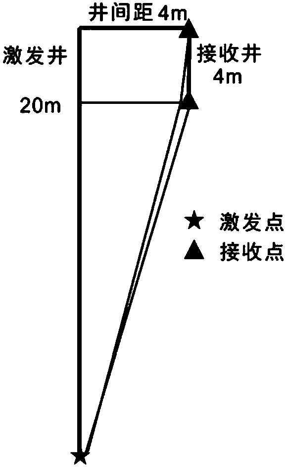
[0081] Such as figure 1 As shown, a two-well micro-logging observation system with one shot excitation and two reception channels is designed. Assume a near-surface depth of 4 meters. The depth of the excitation well is 20 meters, and the bottom of the well is used for excitation, and the excitation depth is 20 meters. The depth of the receiving well is 4 meters, and a geophone of the same type is installed at the wellhead and the bottom of the well. The well spacing is 4 meters.

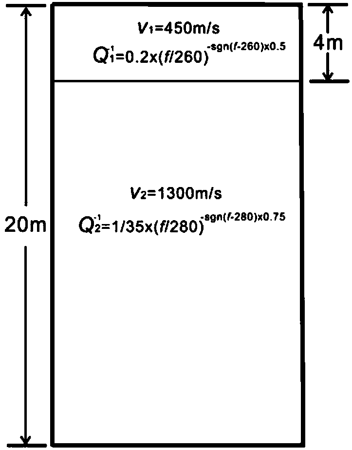
[0082] Such as figure 2 As shown, the design model is that the velocities of the low-velocity layer and the deceleration layer are respectively v 1 =450m / s,v 2 =1300m / s; the quality factors of the low-velocity layer and the decelerating layer are respectively (i.e. Q -1 (f 0 )=0.2, f ...

Embodiment 2

[0086] Example 2: Actual Data

[0087] Such as Image 6 As shown, this embodiment is an application example of block A of an oil field. The terrain in this area is flat, and the near-surface structure is relatively simple. It is divided into two sets of strata, the low-velocity layer and the velocity-reducing layer. The thickness of the low-velocity layer is about 4 meters, and the thickness of the velocity-reducing layer is more than 40 meters. In the stimulation well, the minimum depth of the stimulation well is 2 meters, the maximum depth of the stimulation well is 16 meters, the depth of the shot point is 2 meters apart, and a total of 8 shots are fired. In the receiving well, a geophone of the same type is arranged at the wellhead and the bottom of the well respectively. Well spacing is 4m. The invention extracts 16 meters from the bottom of the well for excitation, and the two channels received by the well head and the bottom of the well carry out nonlinear inversion ...


PUM


Abstract

The invention provides a simulated annealing-based quality factor Q nonlinear inversion method and system. The method includes the following steps that: a dual-well micro logging observation system isutilized to obtain micro logging data; direct waves excited by the same shot are extracted from the micro logging data, and an attenuation curve is calculated; the prior information of the change ofa quality factor Q with a frequency is introduced, a nonlinear objective function is established based on the attenuation curve; a simulated annealing method is adopted to obtain parameters in the objective function by means of nonlinear inversion, so that the value of the quality factor Q which changes with the frequency is obtained. Compared with the prior art, a constant Q hypothesis is avoided, and the value of the frequency-dependent quality factor Q is directly obtained; and therefore, the accurate compensation of energy lost in formation absorption can be benefitted, and a data foundation is provided for high-precision imaging. With the method adopted, error introduced by a constant Q hypothesis-based inversion method in traditional methods can be eliminated, so that the accuracy ofthe calculation of the value of the quality factor Q can be improved; and the micro logging data are adopted, so that the accuracy and stability of results can be improved.

Description

technical field [0001] The invention relates to the technical field of geophysical exploration, and specifically designs a near-surface Q value modeling technology using simulated annealing nonlinear inversion, which can be applied to seismic data processing in petroleum geophysical exploration. Background technique [0002] Due to the viscoelastic effect of the formation, seismic waves will experience frequency absorption and phase distortion during propagation, which seriously reduces the resolution of seismic data. The quality factor Q can quantitatively describe the attenuation. The resolution and energy of seismic data can be restored by calculating the Q value accurately and using inverse Q filtering. Therefore, how to obtain the Q value accurately is the key. [0003] At present, the calculation method of Q value is based on the assumption of constant Q, that is, it is assumed that Q does not change with frequency, and the spectral ratio method is the most commonly ...

Claims


Application Information

Patent Timeline
Patent Type & Authority Applications(China)
IPC IPC(8): G01V1/30
CPCG01V1/306G01V2210/6169G01V2210/624G01V2210/66
Inventor 郑浩蔡杰雄郭恺王守进
Owner CHINA PETROLEUM & CHEM CORP
Why Eureka
Try Eureka