Polarizing structure, display panel and display device

A display panel and polarizing technology, applied in optics, nonlinear optics, instruments, etc., can solve the problems of small viewing angle, high cost, and poor side-view image quality, and achieve the effect of solving color shift

Inactive Publication Date: 2019-01-04
HKC CORP LTD +1
View PDF7 Cites 8 Cited by
  • Summary
  • Abstract
  • Description
  • Claims
  • Application Information

AI Technical Summary

Problems solved by technology

[0003] Based on this, it is necessary to provide a polarizing structure, a display panel and a display device for the problems of small display viewing angle, poor side-view image quality, and high cost of the display device.

Method used


Image

  • Polarizing structure, display panel and display device
  • Polarizing structure, display panel and display device
  • Polarizing structure, display panel and display device

Examples


Embodiment Construction

[0034] In order to facilitate the understanding of the present application, the present application will be described more fully below with reference to the relevant drawings. Preferred embodiments of the application are shown in the accompanying drawings. However, the present application can be embodied in many different forms and is not limited to the embodiments described herein. On the contrary, the purpose of providing these embodiments is to make the disclosure of the application more thorough and comprehensive.

[0035] It should be noted that when an element is referred to as being “fixed” to another element, it can be directly on the other element or there can also be an intervening element. When an element is referred to as being "connected to" another element, it can be directly connected to the other element or intervening elements may also be present. The terms "vertical," "horizontal," "left," "right," and similar expressions are used herein for purposes of ill...


PUM


Abstract

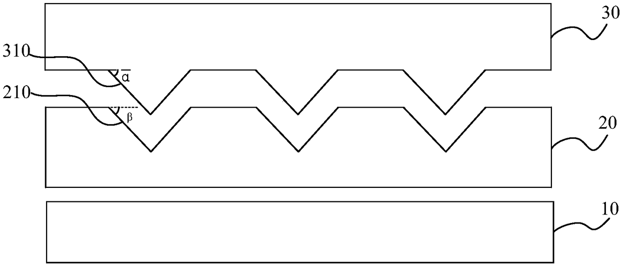
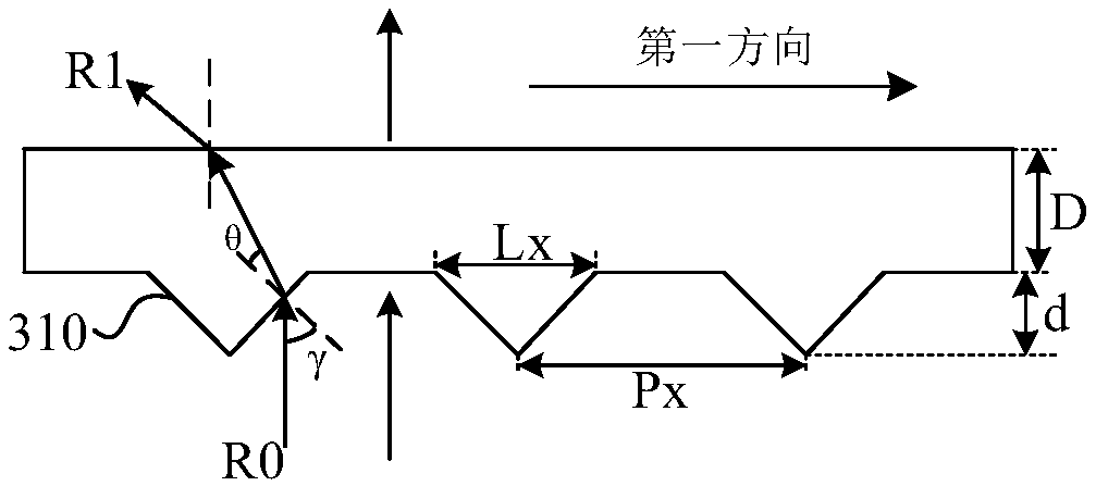
The invention relates to a polarizing structure, comprising: a polarizing film; a supporting protective film comprising a light incident surface and a light emitting surface, wherein the light incident surface is in contact with the polarizing film, a plurality of grooves with preset shapes are formed in the light emitting surface of the supporting protective film, and an included angle between aside face of each groove and the light incident surface is an acute angle; an optical compensation film, wherein the optical compensation film is formed on the light emitting surface of the supportingprotective film; the first refractive index of the optical compensation film is greater than the second refractive index of the supporting protective film; and a plurality of protrusion structures matching the shapes and sizes of the grooves are formed in one surface of the supporting protective film in contact with the supporting protective film. According to the polarizing structure provided bythe invention, by setting the optical compensation film, the light incident perpendicularly to the optical compensation film can be refracted, so that the light energy of a positive viewing angle isallocated to a side viewing angle to solve the problem of color cast. Since the entire polarizing structure does not use additional metal wiring, there is no problem of affecting the transmissivity oflight.

Description

technical field [0001] The present application relates to the field of display technology, in particular to a polarizing structure, a display panel and a display device. Background technique [0002] With the development of display technology, liquid crystal display devices are widely used due to their advantages of high image quality, power saving, thin body, etc. Among them, the quality of image quality is the most important factor affecting consumer experience. A liquid crystal display device is generally composed of a backlight module and a display panel placed on the backlight module. The backlight module provides incident light for the display panel. The incident light is usually concentrated and vertically incident on the display panel. , can obtain better display quality, but when the display is viewed from the side view direction, the picture quality is poor and the color shift is serious, which makes the viewing angle of normal display smaller. At present, the typ...

Claims


Application Information

Patent Timeline
Patent Type & Authority Applications(China)
IPC IPC(8): G02F1/1335G02F1/13363
CPCG02F1/133528G02F1/13363
Inventor 康志聪
Owner HKC CORP LTD
Why Eureka
Try Eureka