Capacitor mounting structure

A mounting structure and capacitor technology, applied in the direction of capacitors, electrical components, etc., can solve the problems of weakened mounting board structure, irregular arrangement, heavy weight, etc., achieve convenient and fast installation and disassembly, improve electrical performance, and improve work efficiency Effect

Inactive Publication Date: 2019-01-04
CHANGZHOU BORI ELECTRIC POWER AUTOMATION EQUIP +2
View PDF5 Cites 3 Cited by
  • Summary
  • Abstract
  • Description
  • Claims
  • Application Information

AI Technical Summary

Problems solved by technology

The method of splicing multiple capacitor modules is not only cumbersome in disassembly and assembly steps, but also takes up a large space, and has no advantages in assembly accuracy and maintainability
The installation method of pull-out drawer is adopted, and the reactor, contactor or thyristor module, vertical busbar and other structures are all set on the same module, and the whole module needs to be pulled out during maintenance, which is not convenient and fast enough for maintenance, and the components Arranged irregularly on the modules, the internal structure is messy and unsightly
Under the necessary condition of satisfying the creepage distance, there are two main ways to design the structure of the existing capacitor module. One design way is to increase the arrangement distance between the capacitors to meet the requirement of the creepage distance. This design The structure of the capacitor mounting plate becomes very large, and the space occupied by the overall structure of the capacitor assembly is greatly increased; another design method is to open a hole on the mounting plate, and install the capacitor in the through hole of the mounting plate through fasteners such as screws, so structure, the structural strength of the mounting plate will be greatly weakened. Considering the weight of the capacitor is large, it is impossible to arrange more capacitors

Method used


Image

  • Capacitor mounting structure
  • Capacitor mounting structure
  • Capacitor mounting structure

Examples


Embodiment Construction

[0022] In order to make the content of the present invention more clearly understood, the present invention will be further described in detail below based on specific embodiments and in conjunction with the accompanying drawings.

[0023] Unless otherwise defined, the technical terms or scientific terms used herein shall have the usual meanings understood by those skilled in the art to which the present invention belongs. "First", "second" and similar words used in the patent specification and claims of the present invention do not indicate any order, quantity or importance, but are only used to distinguish different components. Likewise, words like "a" or "one" do not denote a limitation in quantity, but indicate that there is at least one.

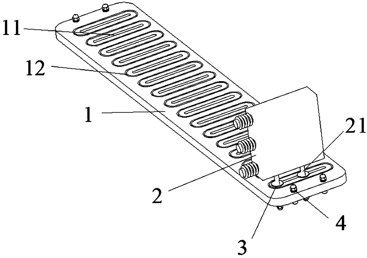
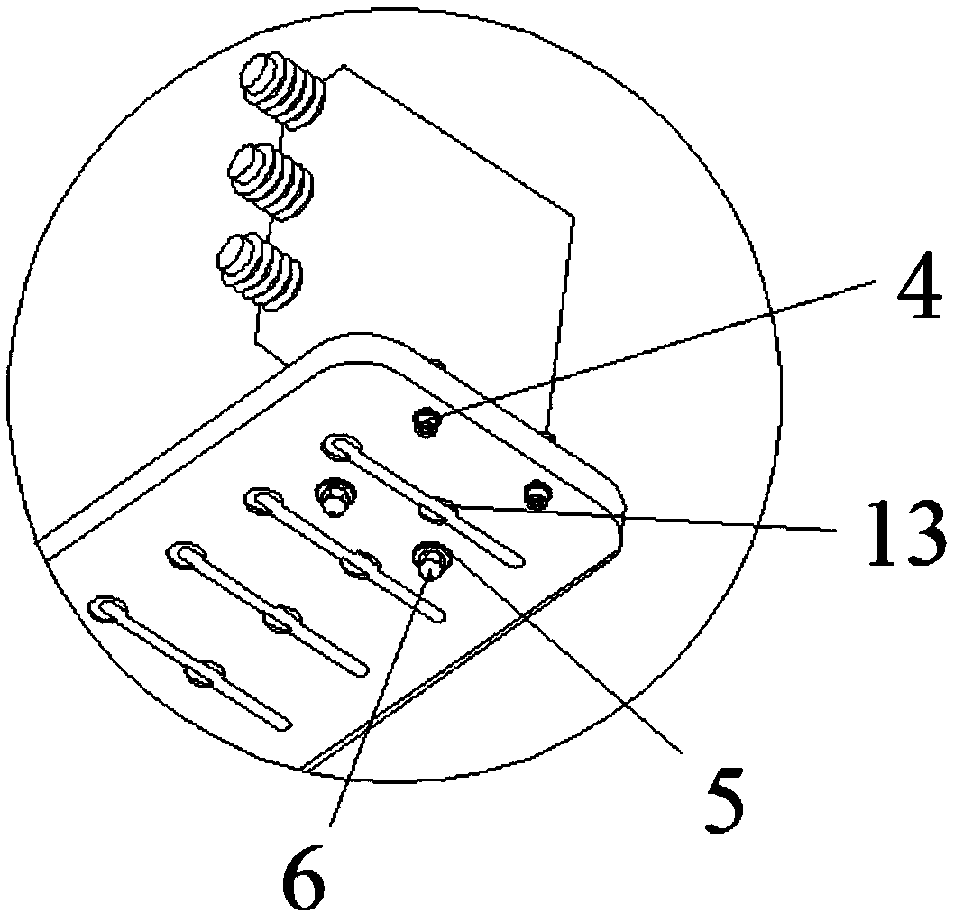
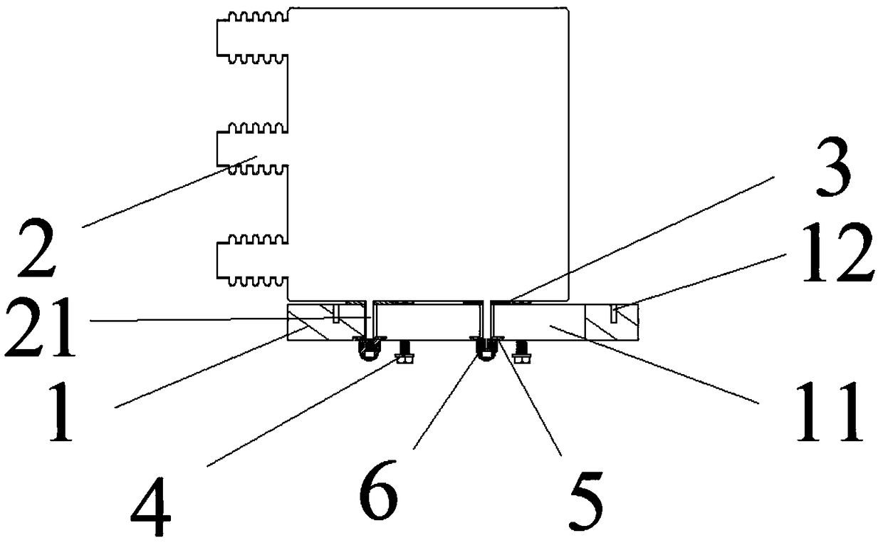
[0024] The invention aims to meet the application in the technical field of electric power automation equipment, especially the capacitor assembly structure of high-power equipment, and pays attention to the fast disassembly and assembl...


PUM


Abstract

The invention discloses a capacitor mounting structure, comprising a mounting plate, wherein a plurality of mounting positioning through-grooves are arranged on the mounting plate, the mounting positioning through-grooves are used for mounting capacitors, and the capacitor is detachably mounted on the mounting positioning through-grooves of the mounting plate; capacitors, wherein one sides of thecapacitors are fixedly connected with a connecting rod for connecting with the mounting plate, the connecting rod penetrates the mounting positioning through-groove and can slide along the mounting positioning through-groove; The capacitor is screwed on the mounting positioning through-groove by the connecting rod on the capacitor through the nut; and an insulating gasket sleeving the connecting rod and interposed between the capacitor and the mounting plate to increase the creepage distance between the capacitors. It does not increase the size of the mounting plate and does not reduce the mechanical strength of the mounting plate, which can improve the electrical performance of the assembly as far as possible under the limitation of the structural space.

Description

technical field [0001] The invention relates to a capacitor installation structure, which belongs to the technical field of electric power automation equipment. Background technique [0002] Most of the existing capacitor module structures are spliced ​​or drawn out. The method of splicing multiple capacitor modules is not only cumbersome in disassembly and assembly steps, but also takes up a large space, and has no advantages in assembly accuracy and maintainability. The installation method of pull-out drawer is adopted, and the reactor, contactor or thyristor module, vertical busbar and other structures are all set on the same module, and the whole module needs to be pulled out during maintenance, which is not convenient and fast enough for maintenance, and the components The modules are arranged irregularly, and the internal structure is messy and unsightly. Under the necessary condition of satisfying the creepage distance, there are two main ways to design the structur...

Claims


Application Information

Patent Timeline
Patent Type & Authority Applications(China)
IPC IPC(8): H01G2/04
CPCH01G2/04
Inventor 李钊谢鸟龙叶松张子敬张如印
Owner CHANGZHOU BORI ELECTRIC POWER AUTOMATION EQUIP
Why Eureka
Try Eureka